Self-controlled heating welding electric circuit device

A circuit device and gas circuit technology, applied in the direction of circuits, auxiliary devices, electrical components, etc., can solve the problems of potential safety hazards, resource waste, long-time ignition, etc., and achieve a safe and reliable working environment, prevent burning waste, and easy operation Effect

Active Publication Date: 2014-11-26
ZHEJIANG CHUANGYUAN LIGHTING TECH +1
View PDF5 Cites 0 Cited by
  • Summary
  • Abstract
  • Description
  • Claims
  • Application Information

AI Technical Summary

Problems solved by technology

If the gas is adjusted every time welding, it will be more troublesome; if frequent adjustment of the gas is avoided, the ignition needs to be kept for a long time, resulting in waste of resources
Moreover, when the gas adjustment ratio is incorrect, it is very easy to cause an explosion
[0003] CN2711891Y (2005-07-20) discloses an improved circular fluorescent lamp tube bending machine, which adjusts the ratio of fuel gas, oxygen and air to control the temperature of combustion through various manual regulating valves in the pipeline. There are many switches and regulating valves, the operation is complicated and has potential safety hazards

Method used


Image

  • Self-controlled heating welding electric circuit device
  • Self-controlled heating welding electric circuit device

Examples


Embodiment 1

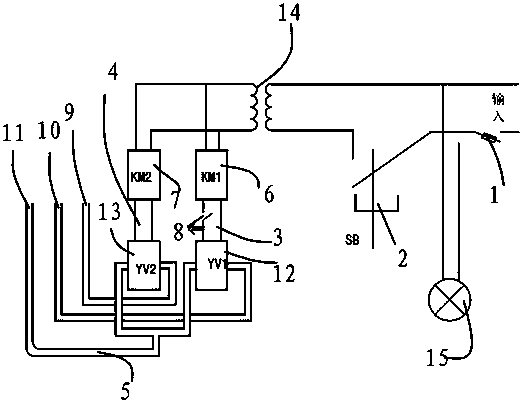
[0024] like figure 1 As shown, the electrical circuit device for self-controlled heating welding includes a voltage input port 1, a main power switch 2, a first gas circuit 3, a second gas circuit 4 and a third gas circuit 5, and the first gas circuit 3 includes the first gas circuit connected in sequence. A control electric contactor 6, the inlet of the first solenoid valve 12 and the liquefied gas inlet 10, the second gas circuit 4 includes the second control electric contactor 7, the inlet of the second solenoid valve 13 and the oxygen inlet 9 connected in sequence, the first The three gas circuit 5 includes the mixed gas outlet 11 formed after the outlet of the first solenoid valve 12 and the outlet of the second solenoid valve 13 merge. A step-down transformer 14 is set between them, and the 220V input from the input voltage port is transformed into a safe voltage of 24V. The electrical circuit setting of this device is through the joint action of two electric control co...

Embodiment 2

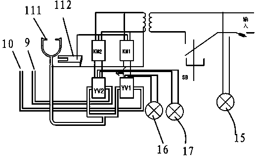
[0027] like figure 2 As shown, the electric circuit device of self-controlled heating welding is the same as that of Embodiment 1, the difference is that the mixed gas outlet 11 is provided with a U-shaped fire head gun 111, and the mixed gas outlet 11 is connected to the output area of ​​the step-down transformer 14; the first control electrical contact The entrance of device 6 and the second control electrical contactor 7 is connected with draw-in groove 112, and draw-in groove 112 is provided with U-shaped notch, and fire head gun 111 is a three-way structure, and fire head gun 111 can be hung on the notch of draw-in groove 112. When the muzzle gun 111 is hung on the slot 112, that is, when the two are in contact with each other, the second gas path is short-circuited, and the oxygen is immediately disconnected. When short-circuited, the solenoid valve does not work, the fire is cut off, and the heating and welding can be controlled conveniently.

[0028] In order to avoi...


PUM


Abstract

The invention relates to an electric circuit applied to the manufacturing of an electrodeless lamp. A self-controlled heating welding electric circuit device comprises a voltage input port, a power supply main switch, a first gas circuit, a second gas circuit and a third gas circuit, wherein the first gas circuit comprises a first electric control contactor, an inlet of a first electromagnetic valve, and a liquefied gas inlet which are connected in turn; the second gas circuit comprises a second electric control contactor, an inlet of a second electromagnetic valve, and an oxygen inlet which are connected in turn; the third gas circuit comprises a mixed gas outlet formed by joining an outlet of the first electromagnetic valve and an outlet of the second electromagnetic valve; and a step-down transformer is arranged between the power supply main switch and the first gas circuit, and between the power supply main switch and the second gas circuit respectively. The self-controlled heating welding electric circuit device can automatically adjust the ratio of mixed gas, opens and closes a welding fire head through the opening and closing of the electric control contactors and a short circuit principle, and fulfills the technical aims that the device is convenient to use, is safe and reliable and saves energy.

Description

technical field [0001] The invention relates to an electric circuit used in the preparation of an electrodeless lamp. Background technique [0002] In the prior art, especially in the preparation process of the electrodeless lamp, the mixed gas of liquefied gas and oxygen is generally used as the gas source for heating and welding, and the ratio of the mixed gas needs to be adjusted before welding. If the gas is adjusted every time welding, it will be more troublesome; if frequent adjustment of the gas is avoided, the ignition needs to be kept for a long time, resulting in waste of resources. Moreover, when the gas adjustment ratio is incorrect, it is extremely easy to cause an explosion. [0003] CN2711891Y (2005-07-20) discloses a kind of improved circular fluorescent lamp tube bending machine, it adjusts the gas, oxygen and air ratio to control the temperature of combustion through various manual regulating valves in the pipeline, but this device is due to the There are...

Claims


Application Information

Patent Timeline
Patent Type & Authority Patents(China)
IPC IPC(8): B23K37/00H01J9/00
Inventor 张顺清张汉兵
Owner ZHEJIANG CHUANGYUAN LIGHTING TECH
Why Eureka
Try Eureka