Reversing valve and combustion engine with the reversing valve

A technology of internal combustion engine and reversing valve, which is applied in the direction of engine components, engine control, machine/engine, etc., to achieve the effect of expanding the application range

Inactive Publication Date: 2011-10-12
DR ING H C F PORSCHE AG
View PDF4 Cites 36 Cited by
  • Summary
  • Abstract
  • Description
  • Claims
  • Application Information

AI Technical Summary

Problems solved by technology

But such a scheme would require massive changes to the internal combustion engine

Method used


Image

  • Reversing valve and combustion engine with the reversing valve
  • Reversing valve and combustion engine with the reversing valve
  • Reversing valve and combustion engine with the reversing valve

Examples


Embodiment Construction

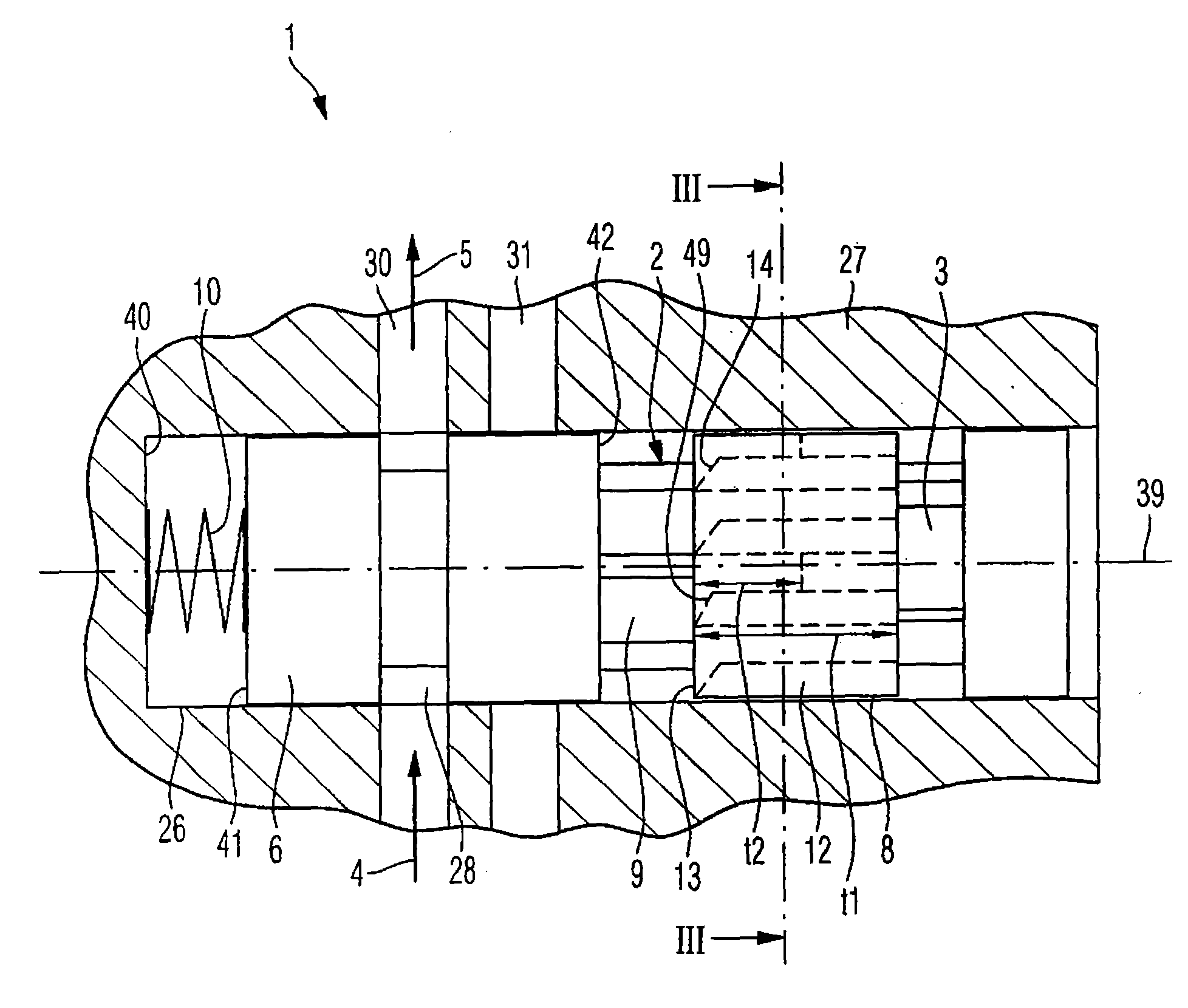
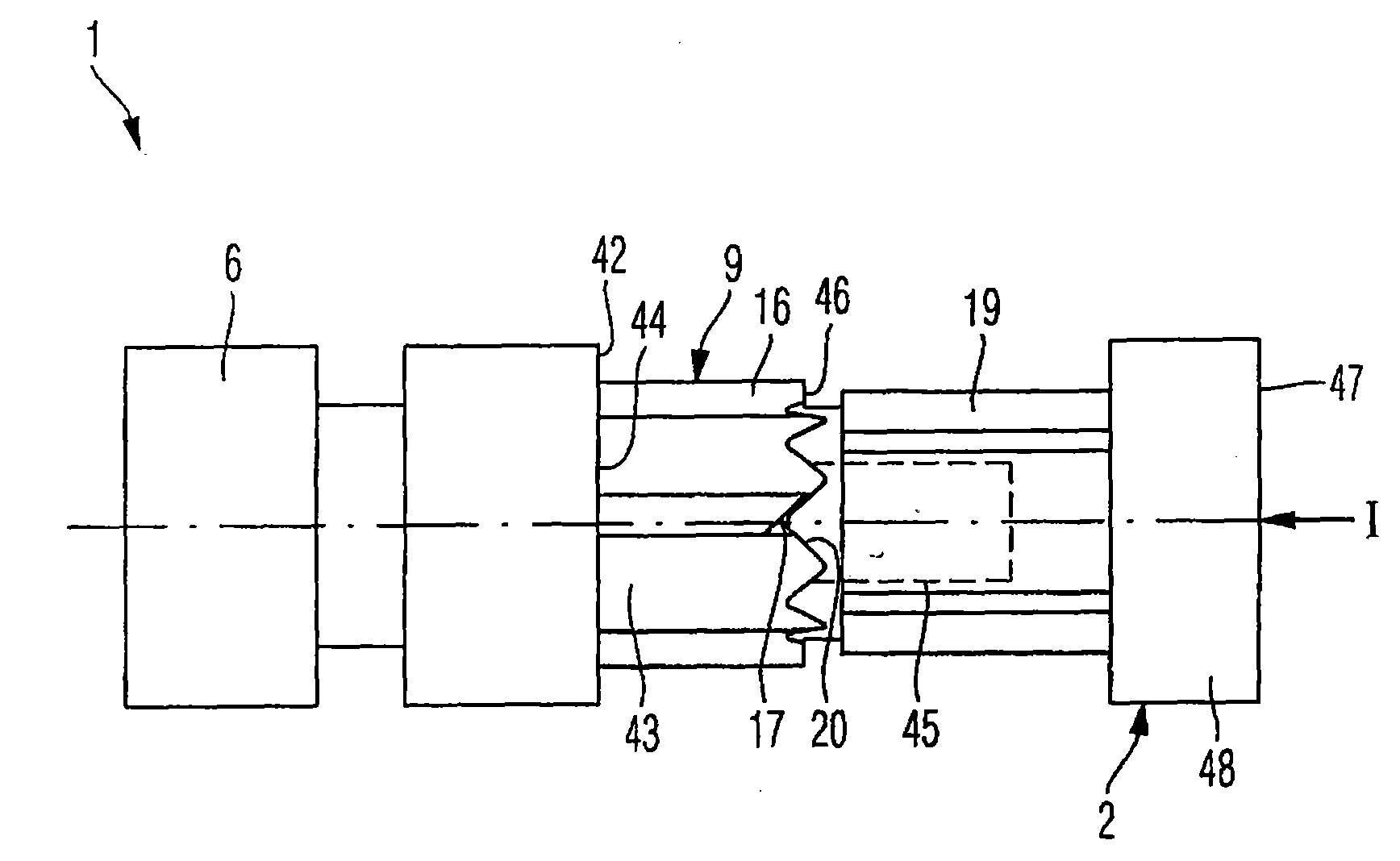
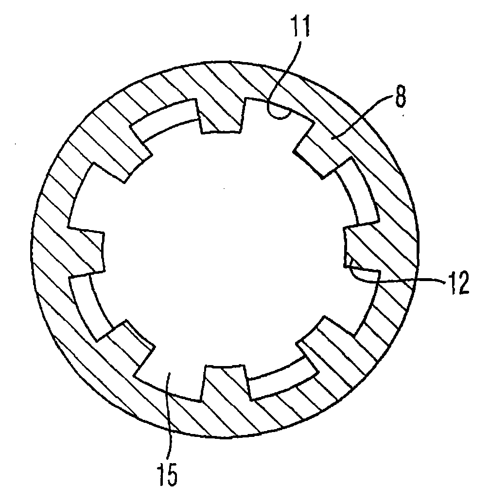
[0039] The following are also used for reference Figure 1 to Figure 5 A first exemplary embodiment of a directional control valve 1 with a ballpoint pen mechanism 2 , in particular for controlling hydraulic fluid flows, is shown in a first switching position. The directional control valve 1 has a control piston 6 with a fluid groove 28 . The control piston 6 has a cylindrical basic shape, wherein a fluid groove 28 in the form of an annular groove 28 is arranged in an outer surface of the control piston 6. The control piston 6 is arranged, for example, preferably axially displaceable in a valve opening 26 of the directional control valve 1 . The valve bore 26 is preferably arranged in a valve body 27 . A plurality of fluid conduits 30 , 31 passing through the valve hole 26 are disposed in the valve body 27 . The fluid lines 30 , 31 are here arranged axially along a central axis 39 of the valve opening 26 , preferably spaced apart from one another. The valve bore 26 is pref...


PUM


Abstract

The invention relates to a reversing valve (1), particularly a reversing valve (1) with a ballpoint pen mechanism (2) for controlling hydraulic fluid flow. The ballpoint pen mechanism can be alternately latched in a first or a second positions and is coupled with the reversing valve (1) by applying a control pulse (I) on the actuation means (3) of the ballpoint pen mechanism (2), so that the first or the second position is respectively correspondent to the first or the second switch positions of the control piston (6) of the reversing valve (1). The invention further relates to a combustion engine having an adjustable compression ratio, which comprises the above reversing valve (1) and a connection rod arrangement (3). The connection rod arrangement (3) has an eccentric device (36) capable of being adjusted in a hydraulic mode, which is arranged inside a connection rod bearing hole (34) and/or a crane bearing hole (35) for adjusting the effective length of the connection rod (leff). The adjusting stroke of the eccentric device (36) can be controlled by the reversing valve (1).

Description

technical field [0001] The invention relates to a directional valve, in particular for controlling the flow of hydraulic fluid, and to an internal combustion engine having a directional valve of this type. Background technique [0002] Although the invention and the problem underlying it can be applied to any vehicle, it is described in detail here with reference to a passenger car. [0003] In internal combustion engines, a high compression ratio has a positive influence on the efficiency of the internal combustion engine. The term "compression ratio" is generally understood to mean the ratio of the total cylinder volume before compression to the remaining cylinder volume after compression. However, in externally ignited internal combustion engines (especially Otto engines) with a fixed compression ratio, the magnitude of the compression ratio can only be selected in such a way that the so-called internal combustion engine failure is avoided during full load operation. "D...

Claims


Application Information

Patent Timeline
Patent Type & Authority Applications(China)
IPC IPC(8): F16K13/00F02B75/04F02D15/02
CPCF02B75/045F16K11/07F16K31/122F16K31/52483F16K31/5286F16K31/56F16C7/06F16C23/10
Inventor M·保罗
Owner DR ING H C F PORSCHE AG
Why Eureka
Try Eureka