Evaporator unit

An evaporator and ejector technology, applied in the direction of evaporator/condenser, compressor with multiple evaporators, indirect heat exchanger, etc., can solve the problem that the temperature distribution cannot be fully suppressed and the compressor cycle efficiency cannot be fully , hinder the miniaturization of the evaporator unit, etc., to achieve the effect of increasing the cross-sectional area, improving the circulation efficiency, and suppressing the increase of the pressure loss.

Active Publication Date: 2011-10-12
DENSO CORP
View PDF8 Cites 21 Cited by
  • Summary
  • Abstract
  • Description
  • Claims
  • Application Information

AI Technical Summary

Problems solved by technology

As a result, the temperature distribution of the air blown from the evaporator unit cannot be sufficiently suppressed
[0018] In addition, adding a refrigerant pipe for forcibly guiding the refrigerant flowing out of the ejector to the first evaporator disposed on the windward side hinders the miniaturization of the evaporator unit, and the refrigerant pressurized by the diffuser is Pressure drop due to pressure loss in refrigerant piping
As a result, the cycle efficiency (COP) improvement effect of reducing the power consumption of the compressor mentioned above cannot be sufficiently obtained.

Method used


Image

  • Evaporator unit
  • Evaporator unit
  • Evaporator unit

Examples


no. 1 approach

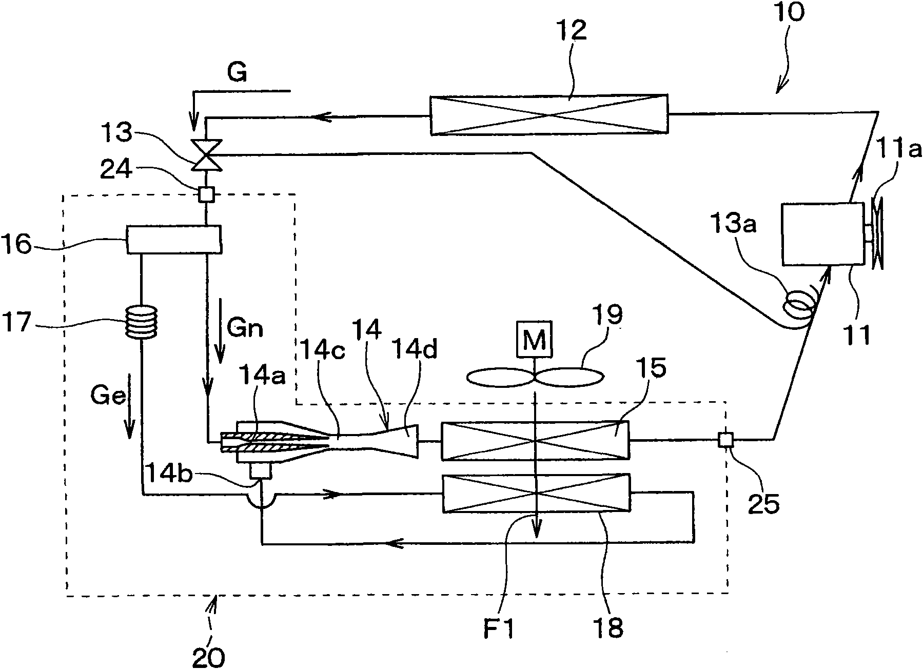
[0077] Hereinafter, a first embodiment of the present invention will be described. figure 1 An example in which the ejector refrigeration cycle 10 of the first embodiment is applied to a refrigeration cycle apparatus for a vehicle is shown.

[0078] existfigure 1 In the illustrated ejector refrigeration cycle 10 , a compressor 11 sucking and compressing refrigerant is driven and rotated by an unillustrated vehicle running engine via an electromagnetic clutch 11 a , a belt, and the like.

[0079] As the compressor 11, a variable capacity compressor capable of adjusting the refrigerant discharge capability according to a change in the discharge container may be used, or the refrigerant may be adjusted by changing the operating rate of the compressor by engaging or disengaging the electromagnetic clutch 11a. Any of the fixed-capacity compressors with discharge capacity. In addition, when an electric compressor is used as the compressor 11, the refrigerant discharge capability ca...

no. 2 approach

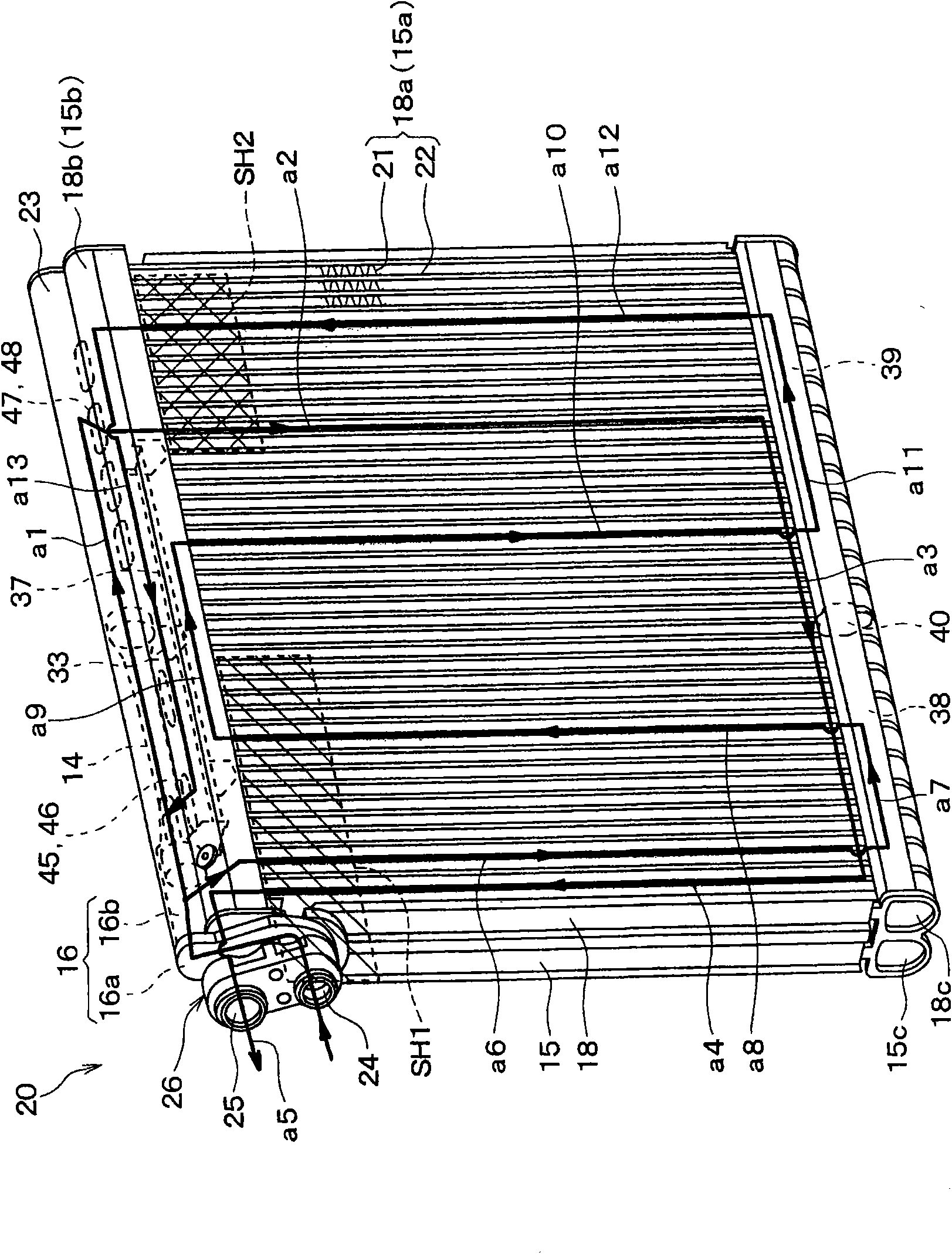
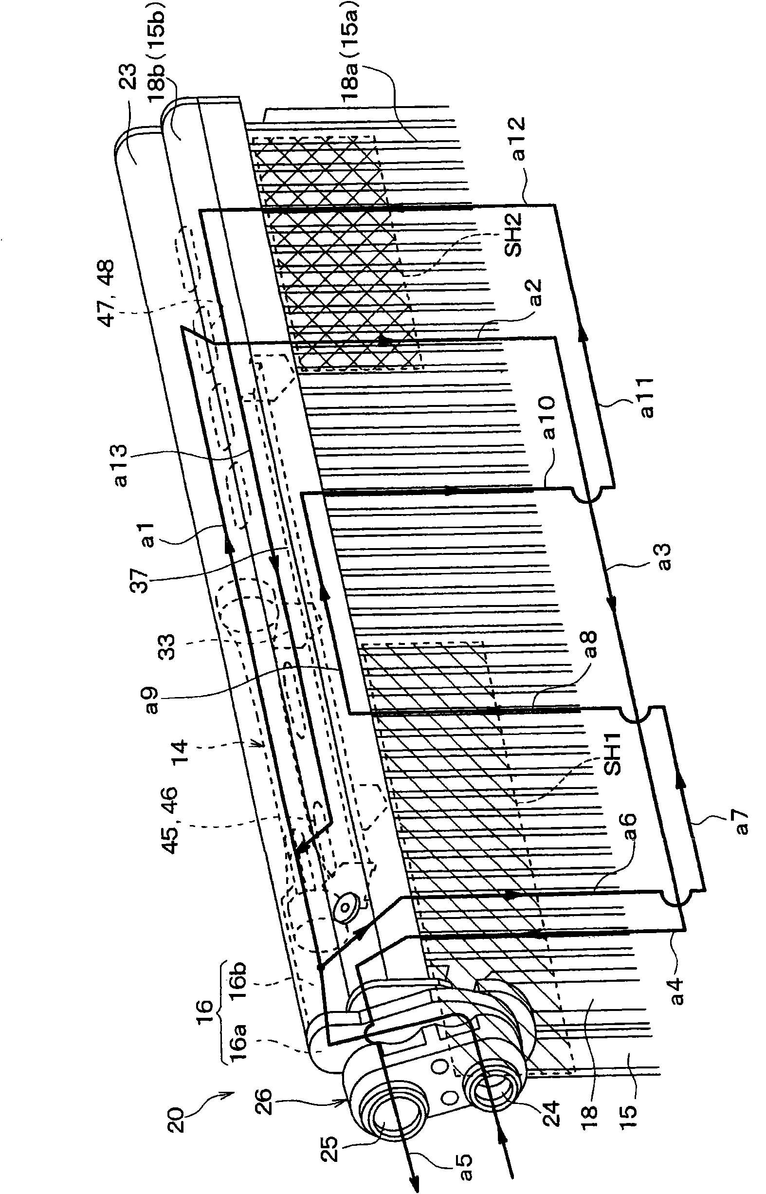
[0229] Figure 19A represents the integrated unit 120 of the second embodiment, Figure 19B express Figure 19A The connector 26. In this second embodiment, if Figure 19A As shown, the first evaporator 15 and the second evaporator 18 form a so-called laminated heat exchanger. That is, the first evaporator 15 and the second evaporator 18 have a tube plate (tube plate) 60 in which the tube 21 is formed by joining a pair of plates, and the first evaporator 15 and the second evaporator 18 have It is constructed by laminating a plurality of tube sheets 60 .

[0230] Specifically, a plurality of flat tubes 21 are formed by stacking aluminum plates that have been press-formed into a predetermined shape and then joined by brazing, and formed at both ends in the longitudinal direction of the tube 11 There are box parts 15b, 15c, 18b, 18c.

[0231] The tube sheet 60 is appropriately formed in a shape for constituting the refrigerant flow paths a1 to a13 similar to those in the fi...

no. 3 approach

[0234] In the above-mentioned first and second embodiments, the evaporator unit 20 used in the ejector refrigeration cycle 10 was described, but in this third embodiment, the evaporator unit 20 used in the expansion valve cycle 100 that does not include the ejector 14 is described. Evaporator unit 120 .

[0235] Such as Figure 20 As shown, in the expansion valve cycle 100 , a liquid receiver 12 a is provided on the outlet side of the radiator 12 . The liquid receiver 12a is a vertically long box-shaped member, and constitutes a gas-liquid separator that separates the gas-liquid of the refrigerant and stores the excess liquid refrigerant in the cycle. The liquid refrigerant is guided from the lower side of the inside of the tank shape to the outlet of the liquid receiver 12a. In addition, the liquid receiver 12a is integrally provided with the radiator 12 in this example.

[0236] In addition, as the radiator 12, a well-known structure having a heat exchange part for conden...


PUM


Abstract

An integrated unit (20) is formed by integrally assembling an ejector (14), a first evaporator (15) that evaporates refrigerant discharged from the ejector, a second evaporator (18) that evaporates the refrigerant drawn into the ejector, a refrigerant dividing portion (16b) that adjusts a flow amount of refrigerant flowing in and divided to the nozzle portion (14a) and the second evaporator, and a joint (26) in which a refrigerant inlet (24) and a refrigerant outlet are formed. In the joint, there is formed a gas-liquid separation portion that causes refrigerant flowing therein to swirl to separate it into gas and liquid. The ejector, refrigerant dividing portion and joint are arranged in a longitudinal direction of the ejector.

Description

technical field [0001] The present invention relates to evaporator units suitable for use in refrigeration cycles. Background technique [0002] Conventionally, Patent Document 1 (JP 2009-222256A) discloses an ejector type refrigeration cycle in which an ejector that functions as a refrigerant decompression mechanism and a refrigerant circulation mechanism is provided on the upstream side. The branch part that branches the flow of the refrigerant flowing out of the radiator, one of the refrigerant discharged from the branch part flows into the nozzle part of the ejector, and the other refrigerant flows into the refrigerant suction port side of the ejector inflow. [0003] In this prior art, the first evaporator is disposed on the downstream side of the diffuser (pressure booster) of the ejector, and the throttle mechanism and the second evaporator are disposed between the branch portion and the refrigerant suction port of the ejector. , so that the cooling capacity can be ...

Claims


Application Information

Patent Timeline
Patent Type & Authority Applications(China)
IPC IPC(8): F25B5/00F25B39/02F25B41/00F25B41/06
CPCF28D1/0333F28D1/0435F28D1/0478F28D1/05375F28D1/05391F28F9/0207F28F9/0251F28F9/026F25B39/022F25B2341/0011F25B2500/01F25B2500/18F25B41/00B60H2001/3298
Inventor 西野达彦中村友彦押谷洋贰又裕文
Owner DENSO CORP
Why Eureka
Try Eureka