A current three-phase linkage switching device

A switching device and three-phase technology, applied in the direction of emergency protection circuit devices, electrical components, prior contact arrangement, etc., can solve the problems of high operating environment requirements, high price, heavy workload, and high cost, so as to improve the operation quality and reduce the Operating procedure, effect of reducing operating load

Active Publication Date: 2015-11-25
JIANGSU ELECTRIC POWER COMPANY YANGZHOU POWER +1
View PDF4 Cites 0 Cited by
  • Summary
  • Abstract
  • Description
  • Claims
  • Application Information

AI Technical Summary

Problems solved by technology

However, at present, the price of foreign protection devices is expensive, and the operating environment requirements are high.
It is directly applied to domestic application sites, and other equipment needs to be updated and modified, and the workload and cost are huge.

Method used


Image

  • A current three-phase linkage switching device
  • A current three-phase linkage switching device
  • A current three-phase linkage switching device

Examples


Embodiment Construction

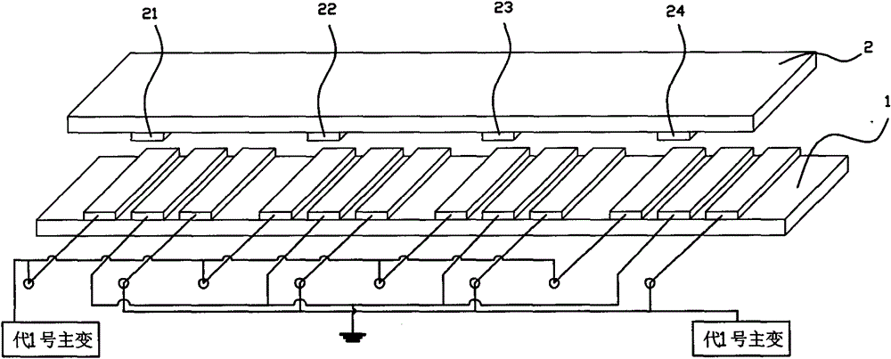
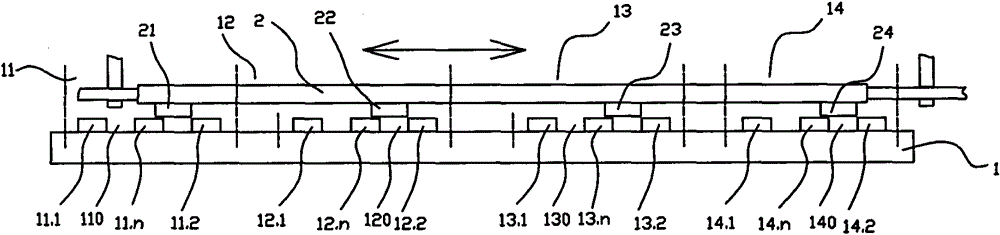
[0032] The invention is like Figure 1-2 As shown, it is used to realize the connection switching between the bypass current and the code No. 1 main transformer and the code No. 2 main transformer. The switching device includes a rectangular insulated moving plate 2 and a fixed plate 1;

[0033] There are four conductive row groups A, B, C, and N (A conductive row group 11, B conductive row group 12, C conductive row group 13, N conductive row group 14) are evenly distributed in the transverse direction of the fixed plate 1, The spacing between the conductive rows of each group is the same. There are three conductive rows in each conductive row group. The three conductive rows are arranged in the order of 1# conductive row, 0# conductive row and 2# conductive row. The separation distance between the row, 0# conductive row and 2# conductive row is the same, and the separation distance is L1 (that is, the A gap 110, the B gap 120, the C gap 130 and the N gap 140 are all L1 in the f...


PUM


Abstract

The invention discloses a current three-phase linked switching device, and relates to an improvement on a current switching device. The switching device can meet the current application situation in China, greatly reduce operating strength, improve operating safety and convenience and avoid misoperation, is used for connecting and switching bypass current between a No.1 main transformer and a No.2 main transformer, and comprises a rectangular insulating movable plate and a rectangular insulating fixed plate, wherein conducting bar groups A, B, C and N are uniformly distributed in the transverse direction of the fixed plate at equal intervals; three conducting bars are arranged in each conducting bar group; lapping bars A, B, C and N are arranged in the transverse direction of the movable plate; the initial positions of the four lapping bars in the transverse direction of the movable plate are respectively consistent with those of 0# conducting bars in the conducting bar groups on the fixed plate in the transverse direction of the fixed plate; and the width of the lapping bars is L3 which is less than L2+2*L1 and more than L1. By the switching device, short circuit, withdrawal, investment and short circuit removing operation which is performed stepwise originally is changed into one-step operation, so that misoperation accidents are avoided.

Description

Technical field [0001] The invention relates to a current switching device for a main transformer differential protection bypass switch in an electric power system, and in particular to an improvement of the current switching device. Background technique [0002] Many current loops in substations need to be switched during operation, such as the current loop switching of the main transformer switch and bypass switch of the main transformer differential protection, and the current loop switching of the bus differential protection; the bypass current is short-circuited and exited under normal circumstances. It can be switched to the "Generation No. 1 Main Transformer" or "Generation No. 2 Main Transformer" position, but it is strictly prohibited to open the circuit during the live switching process. These operations are carried out by the attendant, usually through the current switching pressure plate. These pressure plates are generally divided into four phases (ABCN), and the bi...

Claims


Application Information

Patent Timeline
Patent Type & Authority Patents(China)
IPC IPC(8): H01H1/56H02H7/045
Inventor 李培培陈付陈强于翔
Owner JIANGSU ELECTRIC POWER COMPANY YANGZHOU POWER
Why Eureka
Try Eureka