Rotor winding pole coil and manufacturing die thereof as well as casing copper bar edgewind wrench

A magnetic pole coil and rotor winding technology, which is applied in the field of rotor winding magnetic pole coils, can solve the problems of not meeting the requirements of the flat winding process, the inability to carry out flat winding, and the four corners of the bowl, so as to improve the insulation and heat resistance level and electrical performance, and meet the safety requirements. Reliable operation, the effect of reducing the bending angle

Inactive Publication Date: 2011-10-12
TIANJIN TIRNFR HEAVY HYDROELECTRIC FRCILITY CO LTD
View PDF6 Cites 2 Cited by
  • Summary
  • Abstract
  • Description
  • Claims
  • Application Information

AI Technical Summary

Problems solved by technology

The conventional design of the magnetic pole coil is rectangular, four-corner flat winding structure, the cross-section of the copper bar is (2.5×55), that is, the ratio of width to thickness is more than 20 times, and the number of turns is large. This kind of copper bar does not meet the requirements of the flat winding process. , during the process of edgewise winding of the magnetic pole coil, it is very easy to have a bowl at the four corners, and it is impossible to perform edgewise winding

Method used


Image

  • Rotor winding pole coil and manufacturing die thereof as well as casing copper bar edgewind wrench
  • Rotor winding pole coil and manufacturing die thereof as well as casing copper bar edgewind wrench
  • Rotor winding pole coil and manufacturing die thereof as well as casing copper bar edgewind wrench

Examples


Embodiment Construction

[0020] In order to further understand the invention content, characteristics and effects of the present invention, the following examples are given, and detailed descriptions are as follows in conjunction with the accompanying drawings:

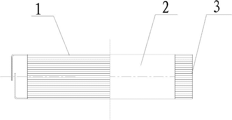
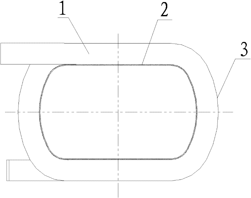
[0021] Such as figure 1 , figure 2 In the rotor winding magnetic pole coil shown, the annular coil 1 is made of copper bars, and the arc angles are formed at the four corners of the annular coil. The length direction of the annular coil is linear, and the width direction of the annular coil is arc-shaped 3. A 0.5 mm glass cloth plate 2 is pasted on the inner diameter of the ring coil.

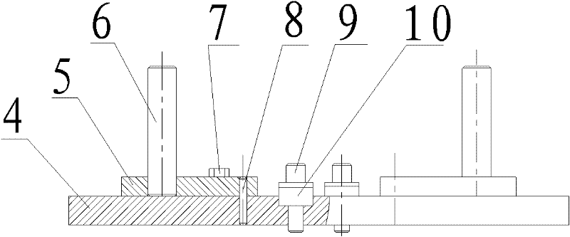
[0022] Such as image 3 , Figure 4 The shown rotor winding magnetic pole coil mold has a bottom plate 4 on which a mold core 5 is symmetrically installed and a column 6 is vertically installed on the mold core. The outer side of the mold core in the width direction is arc-shaped, and the length of the bottom plate is Line crimping hooks 10 are installed ...


PUM


Abstract

The invention relates to a rotor winding pole coil and a manufacturing die thereof as well as a casing copper bar edgewind wrench. The rotor winding pole coil is characterized by comprising an annular coil which is wound by copper bars and arched angles at corners of the annular coil, wherein the annular coil is straight in a length direction and arc-shaped in a width direction; and 0.5mm-thick glass sheets are adhered to the inner diameter of the annular coil. The manufacturing die comprises a baseboard, die cores which are symmetrically arranged on the baseboard and vertical shafts which are vertically arranged on the die cores, wherein the outer side edges of the die cores are arc-shaped in a width direction; and two sides of the baseboard are provided with tension hooks in a length direction. The edgewind wrench comprises tension discs and supporting tube handles which are welded on the tension discs, wherein the tension discs are arc-shaped and the cross sections of the tension discs are T-shaped. According to the invention, the edgewind of a rotor winding pole coil of which the rate of the width and thickness of the cross section of the copper bar is over 15 times for many year is achieved, the efficiency of the winding coil, the radiation and ventilation effects of the rotor winding are improved, and the insulation and heat resistance class as well as electric property of the rotor winding are enhanced.

Description

technical field [0001] The invention relates to a rotor winding pole coil. [0002] The invention also relates to the mold for winding the coil and the flat-wound wrench for the bushing copper bar. Background technique [0003] The company is currently undertaking the task of increasing the capacity of the rotor winding of a water wheel engine. Due to the inter-turn short circuit of the magnetic pole coil of the engine, the hydraulic generator shutdown accident was caused. The solution is: the magnetic pole core does not move, and only the magnetic pole coil is replaced. The conventional design of the magnetic pole coil is rectangular, four-corner flat winding structure, the cross-section of the copper bar is (2.5×55), that is, the ratio of width to thickness is more than 20 times, and the number of turns is large. This kind of copper bar does not meet the requirements of the flat winding process. , during the process of edge-winding the magnetic pole coil, it is very eas...

Claims


Application Information

Patent Timeline
Patent Type & Authority Applications(China)
IPC IPC(8): H02K1/24H02K3/18H02K15/02
Inventor 路春玲李效革张博伟
Owner TIANJIN TIRNFR HEAVY HYDROELECTRIC FRCILITY CO LTD
Why Eureka
Try Eureka