Split-type arrangement method and structure of gas transformer

A gas transformer and layout structure technology, which is applied in transformers, fixed transformers, transformer/inductor cooling, etc., can solve problems such as poor ventilation environment, save floor space, reduce energy consumption and noise, and have good heat dissipation and ventilation effects Effect

Inactive Publication Date: 2016-03-16
CHINA ENERGY ENG GRP GUANGDONG ELECTRIC POWER DESIGN INST CO LTD
View PDF8 Cites 1 Cited by
  • Summary
  • Abstract
  • Description
  • Claims
  • Application Information

AI Technical Summary

Problems solved by technology

[0004] One of the purposes of the present invention is to provide a split layout method for gas transformers in order to solve the problems of poor ventilation environment of the existing gas transformer layout structure and the need for other heat dissipation equipment to be used together
[0005] The second purpose of the present invention is to provide a split layout structure of gas transformers in order to solve the problems of poor ventilation environment and the need for other cooling equipment to be used in the existing gas transformer layout structure

Method used


Image

  • Split-type arrangement method and structure of gas transformer

Examples


specific Embodiment 1

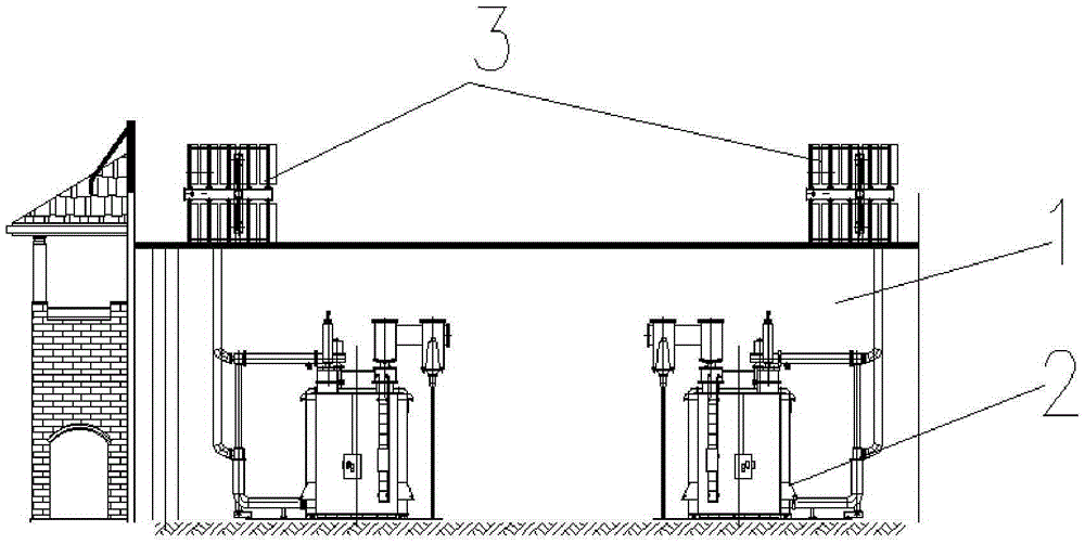
[0024] refer to figure 1 , the split layout structure involved in this embodiment includes a main transformer room 1 and a gas transformer 2, and the heat dissipation structure of the gas transformer 2 is a split independent structure, which constitutes a radiator 3 independent of the gas transformer 1; the gas transformer 2 is arranged In the interior of the main transformer chamber 1, the radiator 3 is arranged outside the main transformer chamber 1 to form a split structure; the fins of the radiator 3 are connected to the gas transformer 2 through heat transfer tubes to form a split heat dissipation structure.

[0025] In this example:

[0026] The main transformer room 1 is located in the semi-underground substation, underground substation or attached substation. The main body of the gas transformer 2 is installed in the semi-basement or basement. The radiator 3 is arranged on the roof of the main transformer room 1 and is in direct contact with the atmosphere. The coolin...

specific Embodiment 2

[0031] The characteristics of this embodiment 2 are: the main transformer room 1 is located in the room of the attached substation, the attached substation is arranged in a large building, the main body of the gas transformer 2 is installed in a special building attached to the large building, The radiator 3 is arranged in the ventilating place in the large building and is in direct contact with the atmosphere, and the fins of the radiator (3) are connected with the main body of the gas transformer 2 through heat transfer tubes. All the other are with specific embodiment 1.

[0032] The applicant's test application has proved that the arrangement method claimed in the present invention cleverly utilizes the insulating medium of the gas transformer 2—SF6 gas has a low density (only 1 / 60 of the insulating oil density) and light weight, and the radiator is flexibly arranged in the The heat dissipation effect is enhanced in a better ventilation environment, so as to better meet th...


PUM


Abstract

The invention relates to a split-type arrangement method and structure of a gas transformer. The split-type arrangement method is characterized by comprising the following steps: 1) preparing the gas transformer and a transformer chamber, setting the gas transformer as a main body and a radiator, and forming two independent individuals, i.e., forming a split-type structure of which the radiator is independent from the main body of the gas transformer; 2) arranging the main body of the gas transformer into the transformer chamber, and arranging the radiator out of the transformer chamber to form the split-type arrangement structure; and 3) connecting the radiator with the main body of the gas transformer by a heat transfer pipeline to cause heat generated by the gas transformer to be transferred to the radiator through the heat transfer pipeline to form an outdoor radiator structure. The radiator of the gas transformer is set into a split-type independent structure to form the radiator independent from the gas transformer. The split-type arrangement structure has the beneficial effects that a radiation and ventilation effect is good, economic cost of radiation is saved and space above the transformer is effectively utilized.

Description

technical field [0001] The invention relates to an arrangement structure of a transformer, in particular to a split arrangement method and structure of a gas transformer, and is especially suitable for installation and setting of a 220kVSF6 gas transformer. It belongs to the technical field of gas transformers. Background technique [0002] In the prior art, most domestic gas-type transformers are arranged in one-piece arrangement, and the heat sink of the transformer is installed on the transformer body. Due to the limitation of the position and space of the transformer room, it is difficult to arrange indoors in the prior art. A good ventilation environment is formed, but the heat dissipation effect is relatively poor, which makes the temperature in the transformer room rise, requiring other ventilation equipment to assist heat dissipation, high operation and maintenance requirements, and the space above the transformer is not effectively used. [0003] Therefore, it is n...

Claims


Application Information

Patent Timeline
Patent Type & Authority Applications(China)
IPC IPC(8): H01F30/06H01F27/20H02B5/00
CPCH01F30/06H01F27/20H02B5/00
Inventor 殷雪莉贺艳芝周敏
Owner CHINA ENERGY ENG GRP GUANGDONG ELECTRIC POWER DESIGN INST CO LTD
Why Eureka
Try Eureka