Single-edge magnetic levitation rotating device adopting double-coil rotating part

A technology of rotating parts and rotating devices, applied in the field of magnetic levitation, can solve problems such as complex structure and adjustment, falling, difficult two-way automatic rotation, etc.

Inactive Publication Date: 2011-10-12
唐建一
View PDF11 Cites 5 Cited by
  • Summary
  • Abstract
  • Description
  • Claims
  • Application Information

AI Technical Summary

Problems solved by technology

[0002] The magnetic levitation device that the magnetic levitation body automatically rotates at the same time as the magnetic levitation, such as patents: ZL99252312.5 and ZL00115354.4, and ZL03141646.2, uses the upper and lower parts of the frame box, and the upper and lower boxes are equipped with elements. Devices, between the upper and lower boxes, there is a hollow conjoined body, which is pierced with wires connecting the upper and lower components, and the upper and lower parts of the maglev body are equipped with permanent magnets, and the maglev body is magnetically floated between the upper and lower boxes; therefore, the maglev It is impossible to completely vacate the top or bottom of the body, which has limitations on the overall shape; if you want: the bottom of the maglev body is completely vacated and rotates automatically, patent: 20041004847.6, using: discrete rotation system, structure and adjustment Complicated, it is difficult to achieve two-way automatic rotation; especially to completely vacate the upper part, it is necessary to use the magnetic floating body to be pushed upward by the magnetic force repelled by the same magnetic force below, which will cause the magnetic floating body to translate, roll over or fly away. Measures. The known method in the past is to set a gyro that can be manually rotated at one time directly above the hollow magnetic ring, and use the magnetic field at the center of the magnetic ring to reverse the conical shape of the lower part of the top gyro. The lower magnetic surface of the same magnetism of the permanent magnet produces the magnetic force of mutual repulsion, supports it up, and utilizes the effect of the "central axis centering" of the inertia of fast flying to make it magnetically levitate in the air, but the energy consumption If it turns slowly, it will fall down; in order to make the magnetic levitation body permanent and stable, it needs power

Method used


Image

  • Single-edge magnetic levitation rotating device adopting double-coil rotating part
  • Single-edge magnetic levitation rotating device adopting double-coil rotating part
  • Single-edge magnetic levitation rotating device adopting double-coil rotating part

Examples


Embodiment 1

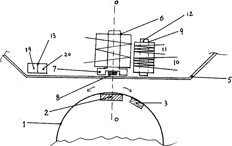
[0023] Embodiment 1: see below floating structure: figure 1

[0024] The centerline 0 of the upper part of the floating magnetic levitation rotor 1 is equipped with a flat magnetic levitation permanent magnet 2, and a permanent magnet 3 for rotation is installed next to it 2, in the box 5 above the magnetic levitation rotor 1 An electromagnet 6 is installed at the center line 0 of the center line, and the opening end of the iron core 7 of its 6 is facing downward, and a Hall element 8 is mounted on the opening end of the iron core 7, and a double wire is installed next to the electromagnet 6. Circle 9, it 9 is by two coils (10,11) of induction coil 10 and electromagnetic coil 11 as rotation sensor and is sheathed on the same ferromagnetic core 12 side by side, circuit board 13 is also housed in box body 5, The double coil 9 and the permanent magnet 3 are within the effective magnetic range of each other; the magnetic levitation rotating body 1 performs magnetic levitation and...

Embodiment 2

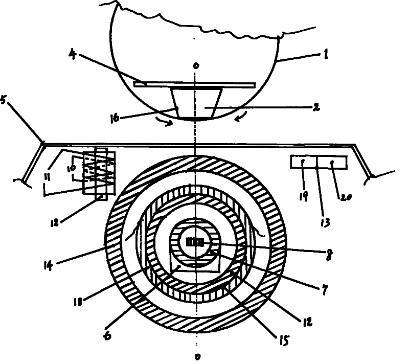
[0025] Embodiment 2: One of the floating structure sees: figure 2

[0026] At the center line 0 of the bottom of the maglev rotating body 1, a flat inverted conical magnetic levitating permanent magnet 2 is installed, and a magnetic guide 4 is mounted on its upper surface, and the box 5 below the maglev rotating body 1 Inside, hollow magnetic ring 14, electromagnet 6, double coil 9, circuit board 13, electromagnetic ring 15 are housed, and this electromagnetic ring 15 is made up of annular ferromagnetic core 12 and coil bag 18; Hollow The magnetic disk 14 is coaxial on the centerline 0 and has longitudinal magnetism. The upward magnetism of the hollow place of the magnetic ring 14 is the same magnetic field as that of the downward magnetic pole surface of the magnetic levitation permanent magnet 2. Then, the magnetic levitation The lower part of the rotating body 1 is floated in the air by the upward lifting force from the middle part of the magnetic ring 14 below, which is ...

Embodiment 3

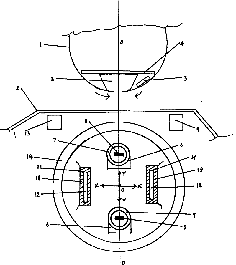
[0027] Embodiment 3: Another structure of floating type sees: image 3


PUM


Abstract

The invention discloses a single-edge magnetic levitation rotating device adopting a double-coil rotating part. The device is divided into upward levitation and downward levitation types. The downward levitation type is characterized in that: an electromagnet which provides a pull-up magnetic levitation force and has a downward opening and the double-coil rotating part which provides a rotating force are arranged in a box body; a magnetic levitation permanent magnet and a rotation magnetic piece are arranged on the upper part of a magnetic levitation rotating body; the magnetic levitation rotating body carries out magnetic levitation and two-way automatic rotation below the box body; and a space below the magnetic levitation rotating body can be completely emptied out. The upward levitation type is characterized in that: a turbinate magnetic levitation permanent magnet and the rotation magnetic piece are arranged on the lower part of the magnetic levitation rotating body; a hollow magnetic ring which provides a lifting force is arranged in the box body below the magnetic levitation rotating body; the electromagnet which provides a downdraft magnetic levitation force and has an upward opening, a limiting coil for centre positioning and double coils are arranged in the ring; by a centripetal electromagnetic component force which is provided by the limiting coil, the slipping, overturning and fly-off of the magnetic levitation rotating body during levitation by the lifting force below the magnetic levitation rotating body can be avoided, so the magnetic levitation rotating body can stably carry out magnetic levitation and two-way random automatic rotation above the box body, and the space above the magnetic levitation rotating body can be completely emptied out. The device is elegant in appearance and has a better magnetic levitation visual effect.

Description

[0001] Technical field: Magnetic levitation, especially magnetic levitation device technical background: [0002] The magnetic levitation device that the magnetic levitation body automatically rotates at the same time as the magnetic levitation, such as patents: ZL99252312.5 and ZL00115354.4, and ZL03141646.2, uses the upper and lower parts of the frame box, and the upper and lower boxes are equipped with elements. Devices, between the upper and lower boxes, there is a hollow conjoined body, which is pierced with wires connecting the upper and lower components, and the upper and lower parts of the maglev body are equipped with permanent magnets, and the maglev body is magnetically floated between the upper and lower boxes; therefore, the maglev It is impossible to completely vacate the top or bottom of the body, which has limitations on the overall shape; if you want: the bottom of the maglev body is completely vacated and rotates automatically, patent: 20041004847.6, using: di...

Claims


Application Information

Patent Timeline
IPC IPC(8): H02N15/00
Inventor 唐建一
Owner 唐建一
Why Eureka
Try Eureka