
Measuring system for ophthalmic surgery

A measurement system, ophthalmic surgery technology, used in ophthalmic surgery, ophthalmoscopy, medical science, etc., to achieve the effect of large working distance

Active Publication Date: 2011-10-12
CARL ZEISS MEDITEC AG
View PDF6 Cites 12 Cited by
  • Summary
  • Abstract
  • Description
  • Claims
  • Application Information

AI Technical Summary

Problems solved by technology

[0007] However, the wavefront sensors disclosed in the aforementioned documents have only limited utility in surgical procedures because they require a short distance between the object and the optical component closest to the object

Method used


Image

  • Measuring system for ophthalmic surgery
  • Measuring system for ophthalmic surgery
  • Measuring system for ophthalmic surgery

Examples


Embodiment Construction

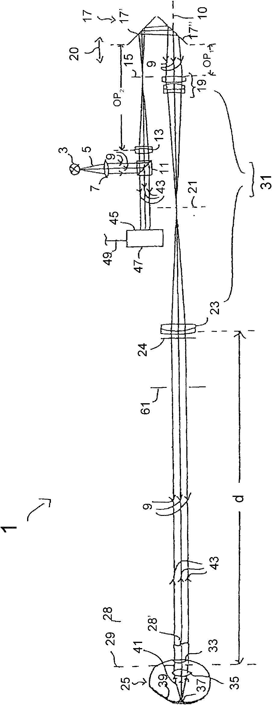
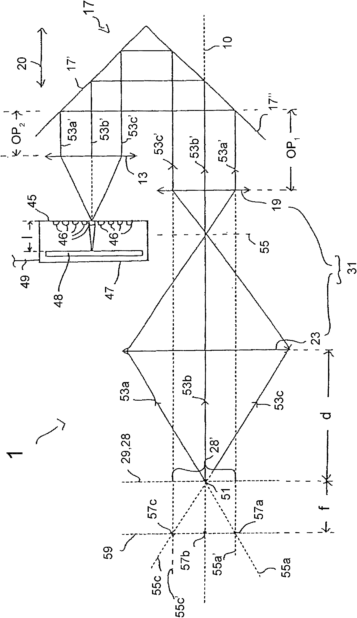
[0084] Figure 1A An optical measuring system 1 according to one embodiment of the invention is schematically shown. The measuring system 1 comprises a light source 3 which generates measuring light 5 . The measurement light 5 is collimated by collimation optics 7 to generate measurement light 9, which substantially consists of a plane wavefront. Measuring light 9 is reflected at beam splitter 11 and passes through adhesive element 13 . The measuring light converged by the adhesive element 13 passes through the aperture 15 and is deflected by 180° by a reflector 17 comprising two mirror surfaces 17' and 17", which are oriented orthogonally to each other. The measurement light 9 is thereby deflected in approximately the opposite direction and displaced in a transverse direction, ie in a direction perpendicular to the direction of propagation of the measurement light 9 .

[0085] In other embodiments, the reflector 17 may be a corner cube. A corner cube consists of a body mad...


PUM


Abstract

The invention relates to an optical measuring system comprising a wave front sensor for characterizing a shape of a wave front of measuring light and an imaging lens, wherein the imaging lens comprises a first optical assembly and a second optical assembly for imaging an object region in an entrance region of the wave front sensor. A distance between the object region and the first optical assembly is larger that a focal length of the first optical assembly. Furthermore, the optical measuring system can comprise an optical microscopy system and optionally an OCT system for carrying out different optical examination methods at the same time.

Description

technical field [0001] The present invention relates to an ophthalmic surgical measurement system with a wavefront sensor and imaging optics. In particular, the present invention relates to an ophthalmic surgical system having a wavefront sensor and imaging optics and being suitable for use in surgery, in particular in ophthalmic surgery, by providing a sufficiently large distance between the imaging optics and the object under examination. measuring system. Furthermore, the invention relates to an ophthalmic surgery measurement system with a wavefront sensor and an OCT system. Background technique [0002] Wavefront sensors configured to characterize the wavefront form of measurement light are known in the art. Such a wavefront sensor can be used specifically to measure the aberrations of the human eye by using a Hartmann-Shack sensor, as described in the papers J.Liang, B.Grimm, S.Goelz, J.F.Bille , "Objective measurement of a Hartmann-Shack wavefront sensor", described...

Claims


Application Information

Patent Timeline
Patent Type & Authority Applications(China)
IPC IPC(8): A61B3/103A61B3/13
CPCA61B3/1015A61F9/00736
Inventor 马库斯·塞萨尔伯格彼得·瑞梅尔克里斯托夫·豪格尔克里斯托夫·库韦布勒
Owner CARL ZEISS MEDITEC AG
Learn More