
High strength and toughness steel structures by friction stir welding

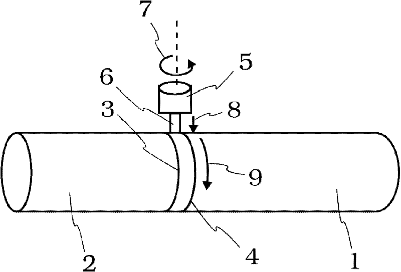
A technology of friction stir welding and steel structure, applied in welding equipment, transportation and packaging, non-electric welding equipment, etc.

Inactive Publication Date: 2011-10-12
EXXON RES & ENG CO
View PDF4 Cites 7 Cited by
  • Summary
  • Abstract
  • Description
  • Claims
  • Application Information

AI Technical Summary

Problems solved by technology

However, for this application, a number of challenges must be overcome in order to accomplish FSW with the widely used fusion welding
A major challenge in determining the technical feasibility of FSW for pipeline connections is obtaining the required strength and stiffness in the joint

Method used


Image

  • High strength and toughness steel structures by friction stir welding
  • High strength and toughness steel structures by friction stir welding
  • High strength and toughness steel structures by friction stir welding

Examples


example 1

[0174] API X80 grade pipeline steel approximately 1 / 2" thick was used in the FSW study. The chemical composition (wt%) of the steel is listed in Table 1. In the examples below, the listed CTOD is the lower bound result.

[0175] Table 1: Chemical composition of steel (wt%):

[0176]

[0177] Steel 1 and Steel 2 with different Nb+Ti contents were chosen to illustrate the effect on fracture stiffness. Steel 1 with a higher Nb+Ti content has better stiffness than Steel 2. Steel 2 also exhibits a significantly larger prior-austenite grain size (40-60 μm) than Steel 1 .

[0178] Figure 7 Transmission electron micrographs are shown showing the presence of high-density, fine precipitates (~10 nm) of NbC and / or Nb(C,N) in Steel 1 . In contrast, steel 2 presents low density, mainly Ti(C,N) coarser precipitates (~200nm).

example 2

[0180] High strength pipeline steel approximately 1 / 2" thick was used in the FSW study. The chemical composition (wt %) of the steel is listed in Table 2.

[0181] Table 2: Chemical composition of steel (wt%):

[0182]

[0183] Tests were carried out on Steel 3 (inventive) and Steel 2 (comparative) to investigate the effect of the primary grain size and microstructure of the steel plates on the mechanical properties of the FSW joints. As mentioned earlier, the initial steel plate grain size reflects the influence of the second phase grains due to TMCP treatment.

[0184] Figure 8 Scanning electron micrographs of the base metal are shown comparing the microstructure of Steel 3 (inventive) and Steel 2 (comparative). In Steel 2, the base metal microstructure is predominantly primary ferrite with a grain size of about 5 μm to about 25 μm. Minute fragments of the second phase are also present in the microstructure, and these domains contain a mixture of martensite, bainite a...


PUM

PropertyMeasurementUnit
Granularityaaaaaaaaaa

Abstract

Provided are steel structures methods of making such steel structures including structural steel components bonded by friction stir weldments with advantageous microstructures to yield improved weldment strength and weldment toughness. In one form of the present disclosure, the steel structure includes: two or more structural steel components produced by conventional melting or secondary refining practices and friction stir weldments bonding faying surfaces of the components together, wherein the chemistry and grain size of the starting structural steel satisfies one or more of the following criteria:; a) 0.02 wt% < Ti + Nb < 0.12 wt%, b) 0.7 < Ti / N <3.5, c) 0.5 wt% < Mo + W + Cr + Cu + Co + Ni < 1.75 wt%, d) 0.01 wt% < TiN + NbC + TiO / MgO < 0.1 wt%, e) average grain size of at least 2 microns, wherein the friction stir weldments have a prior austenite grain size of between 5 and 60 microns and less than 50 vol% of martensite-austenite constituent, and wherein the friction stir weldment strength is greater than the starting structural steel and the friction stir weldment toughness as measured by the crack tip opening displacement test at less than or equal to 0 DEG C is greater than or equal to 0.05 mm or by the Charpy V-notch impact test at less than or equal to 0 DEG C is greater than 40 J. The steel structures find application in linepipe for oil and gas production.

Description

technical field [0001] The present invention relates generally to steel chemistry and steel construction. In particular, the invention relates to steel chemistry and steel structures utilizing friction stir welds. More specifically, the present invention relates to steel chemistry and steel construction utilizing friction stir welds that exhibit advantageous strength and stiffness properties. Background technique [0002] The joining of metal parts such as formed parts, forgings, castings or plates is accomplished primarily by fusion welding to form any number of structures or elements used in various industries. For example, the construction of pipes and tubing to form pipelines for oil, gas and geothermal wells, etc. is primarily accomplished by common arc welding or fusion welding. For decades, the pipeline industry has widely used fusion welding techniques such as shielded metal arc welding (SMAW) and mechanized gas metal arc welding (GMAW) for pipeline construction. ...

Claims


Application Information

Patent Timeline
IPC IPC(8): C22C38/58B23K20/12
CPCB23K20/1225C22C38/001C22C38/02C22C38/06C22C38/44C22C38/48C22C38/50C22C38/54C22C38/58B23K2103/04B23K2103/05Y10T428/12965
Inventor R·艾尔D·P·费尔柴尔德S·J·福特H·金A·奥赛克森
Owner EXXON RES & ENG CO
Learn More