Profiling top-cutting machine for cotton top

A topping machine and cotton technology, which is applied in the direction of agricultural machinery and tools, cutting tools, cutting equipment, etc., can solve the problems of high labor intensity, low operation efficiency, and large limitations of ground profiling, so as to achieve good profiling effect, The effect of simple structure

Inactive Publication Date: 2011-10-19
CHANGJI CHENXIN WEIYE AGRI MACHINERY MFG
View PDF5 Cites 12 Cited by
  • Summary
  • Abstract
  • Description
  • Claims
  • Application Information

AI Technical Summary

Problems solved by technology

[0002] At present, the topping of cotton seedlings in cotton planting operations is done manually, which is labor-intensive and low-efficiency
[0003] Chinese patent CN200810072925.1 discloses a cotton topping machine. The ground is profiled by profiling ground wheels and profiling boots to adjust the height of the topping knife. However, the ground topography differs greatly from the actual growth of cotton. Ground profiling is very limited
[0004] Chinese patent CN200720126953.8 discloses a cotton topping machine with automatic height adjustment. The height of the cotton is detected by an ultrasonic sensor and the topping knife is adjusted by a hydraulic transmission mechanism. The mechanism is too complicated and there are many difficulties in actual implementation.

Method used


Image

  • Profiling top-cutting machine for cotton top
  • Profiling top-cutting machine for cotton top
  • Profiling top-cutting machine for cotton top

Examples


Embodiment 1

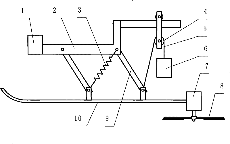
[0018] refer to figure 1 , is a structural schematic diagram of Embodiment 1 of the present invention, comprising a frame 1, a power mechanism, a transmission mechanism and a topping knife 8, a suspension frame 2 is arranged on the frame 1, and a suspension type profiling mechanism is suspended under the suspension frame 2, The suspension-type profiling mechanism includes a telescopic frame 9 and a sliding shoe plate. The projecting knife is arranged on the sliding shoe plate. 2 and the sliding shoe plate 10 are hinged to form a parallelogram four-bar linkage mechanism. The telescopic frame is provided with a spring 3, and the spring 3 is obliquely pulled on the two parallel bars and the suspension frame 2 and the sliding shoe plate 10 are hinged to form a parallelogram four-bar linkage. Between the two opposite obtuse angles of the mechanism, a balance mechanism is provided between the sliding shoe 10 and the suspension frame 9. The balance mechanism includes a pulley mechani...

Embodiment 2

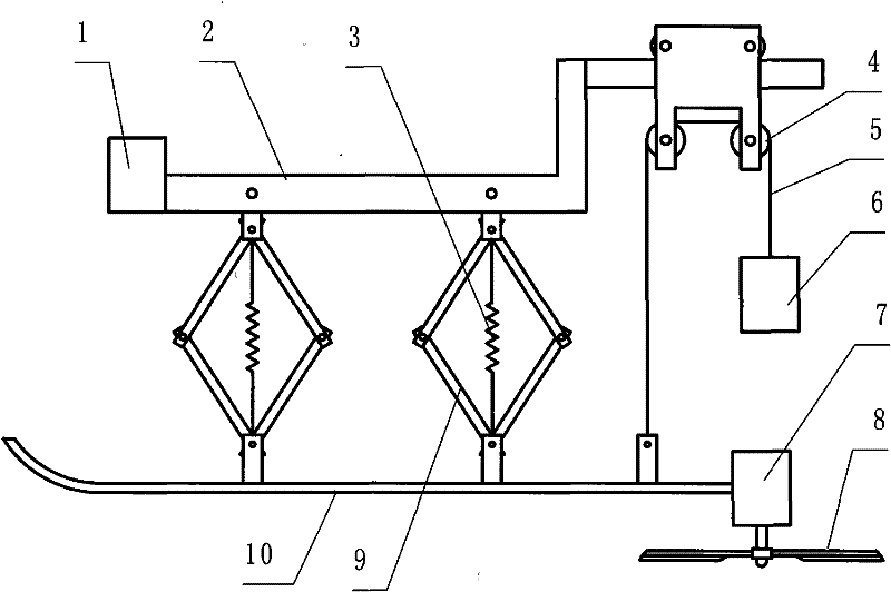
[0020] refer to figure 2 , is a structural schematic diagram of Embodiment 2 of the present invention. Compared with Embodiment 1, the difference of this embodiment is that the telescopic frame 9 is two parallelogram-shaped four-bar linkages, and the parallelogram-shaped four-bar linkages The upper and lower connection points of the mechanism are respectively connected with the suspension frame 2 and the sliding shoe plate 10, the spring 3 is arranged between the upper and lower connection points of the parallelogram four-bar linkage mechanism, and the pulley mechanism is provided with two horizontal pulleys 4, so that Can not interfere with each other between the counterweight 6 and the stay cord 5, and there are two rollers on the upper part of the pulley mechanism to ensure the stability of the pulley mechanism.

Embodiment 3

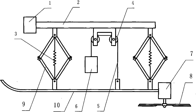
[0022] refer to image 3 , is a schematic structural diagram of Embodiment 3 of the present invention. Compared with Embodiment 2, the difference of this embodiment is that the suspension frame 2 is a horizontal straight rod, and the balance mechanism is arranged between two parallelogram-shaped four-bar linkages , the pulley mechanism is directly fixed on the suspension frame 2.


PUM


Abstract

The invention discloses a cotton top-cutting machine, in particular to a cotton top-cutting machine which can perform profiling according to the height on the top of a cotton plant. The cotton top-cutting machine comprises a machine frame, a power mechanism, a transmission mechanism and a top-cutting cutter, and is characterized in that: a suspension bracket is arranged on the machine frame; a suspension profiling mechanism is suspended below the suspension bracket, and comprises an expansion bracket; the expansion bracket is suspended below the suspension bracket; a sliding boot plate is arranged on the lower part of the expansion bracket; a balance mechanism is arranged between the sliding boot plate and the suspension bracket, and comprises a pulley mechanism consisting of a pulley and a pull rope; one end of the pull rope is connected with the sliding boot plate, and the other end of the pull rope is provided with a balance hammer; and the top-cutting cutter is arranged on the sliding boot plate. Compared with the prior art, the cotton top-cutting machine performs on the height of the cotton plant directly by the expansion bracket and the sliding boot plate which are suspended below the suspension bracket, and is simple in a structure and good in profiling effect.

Description

Technical field: [0001] The invention relates to a cotton topping machine, in particular to a cotton topping machine capable of profiling according to the top height of cotton plants. Background technique: [0002] At present, the topping of cotton seedlings in cotton planting operations is done manually, which is labor-intensive and low-efficiency. [0003] Chinese patent CN200810072925.1 discloses a cotton topping machine. The ground is profiled by profiling ground wheels and profiling boots to adjust the height of the topping knife. However, the ground topography differs greatly from the actual growth of cotton. Ground profiling is very limited. [0004] Chinese patent CN200720126953.8 discloses a cotton topping machine with automatic height adjustment. The cotton height is detected by an ultrasonic sensor and the topping knife is adjusted by a hydraulic transmission mechanism. The mechanism is too complicated and there are many difficulties in actual implementation. I...

Claims


Application Information

Patent Timeline
Patent Type & Authority Applications(China)
IPC IPC(8): A01G3/08
Inventor 宋建民
Owner CHANGJI CHENXIN WEIYE AGRI MACHINERY MFG
Why Eureka
Try Eureka