Material rack component for laser cutter

A laser cutting machine and material rack technology, applied in laser welding equipment, welding equipment, metal processing equipment, etc., can solve the problems of reducing the working efficiency of the laser cutting machine, difficulty in ensuring the flatness of the grid plate, and the non-movable and exchangeable material rack. , to achieve the effect of improving service life, stable and reasonable structure, and cost saving

Inactive Publication Date: 2011-10-19
WUXI HUALIAN PRECISION MACHINERY
View PDF6 Cites 5 Cited by
  • Summary
  • Abstract
  • Description
  • Claims
  • Application Information

AI Technical Summary

Problems solved by technology

[0002] In the machine tool equipment of the prior art, the support grid plate of the material rack for placing the workpiece plate is usually directly inserted on the material rack with a cut straight steel plate, which only plays a simple supporting role, and it is difficult to ensure the stability of the top surface of the grid plate. Flatness, in the cutting process of more sophisticated equipment such as a laser cutting machine, it will directly affect the cutting accuracy of the workpiece; secondly, in the existing technology, the overall material rack is usually not movable and exchangeable, and it needs to be occupied during the loading and unloading process. A lot of time, which seriously reduces the working efficiency of the laser cutting machine

Method used


Image

  • Material rack component for laser cutter
  • Material rack component for laser cutter
  • Material rack component for laser cutter

Examples


Embodiment Construction

[0013] The specific implementation manner of the present invention will be described below in conjunction with the accompanying drawings.

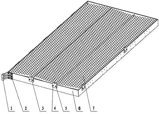
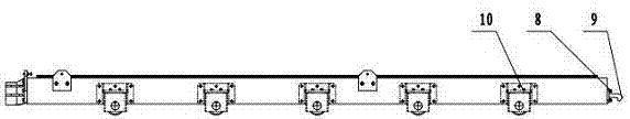
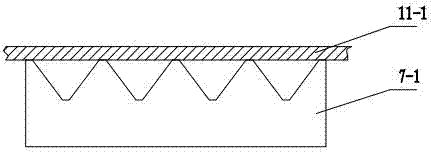
[0014] like Figure 1 to Figure 2 As shown, the laser cutting machine material rack assembly of the present invention includes a transmission hook 1, a screw 2, a hexagon head bolt 3, a positioning plate 4, a screw 5, a material rack frame 6, a support grid plate 7, a screw 8, and a fixing hook 9. Roller assembly 10.

[0015] The present invention adopts that a transmission hook 1 is installed on the front end of the rack frame 6 and fixed with screws 2, the fixed hook 9 is fixed on the rear end face of the rack frame 6 with screws 8, and the positioning plate 4 is respectively installed on the rack frame with screws 5 6 on the front and right sides, the hexagon head bolt 3 is installed in the threaded hole above the positioning plate 4, the support grid plate 7 is inserted into the slot hole on the top of the material rack frame 6, and t...


PUM


Abstract

The invention relates to a material rack component for a laser cutter. A transmission clamping hook is arranged on the front end surface of a material rack frame; a fixed hook is arranged on the rear end surface of the material rack frame; positioning plates are arranged on a group of two adjacent side surfaces of the material rack frame; adjusting bolts are matched with the upper part of the positioning plate by threads; a supporting grating plate is inserted in a slot hole at the internal side of the material rack frame; and rollers are arranged on two external side surfaces of the material rack frame. The material rack component has a stable and reasonable structure, can be operated simply, saves the cost, and effectively improves the cutting precision of a workpiece and the using efficiency of equipment.

Description

technical field [0001] The invention relates to the field of machine tool equipment, in particular to a material rack assembly of a laser cutting machine. Background technique [0002] In the machine tool equipment of the prior art, the support grid plate of the material rack for placing the workpiece plate is usually directly inserted on the material rack with a cut straight steel plate, which only plays a simple supporting role, and it is difficult to ensure the top surface of the grid plate. Flatness, in the cutting process of more sophisticated equipment such as a laser cutting machine, it will directly affect the cutting accuracy of the workpiece; secondly, in the existing technology, the overall material rack is usually not movable and exchangeable, and it needs to be occupied during the loading and unloading process. A lot of time seriously reduces the working efficiency of the laser cutting machine. Contents of the invention [0003] The object of the present inve...

Claims


Application Information

Patent Timeline
Patent Type & Authority Applications(China)
IPC IPC(8): B23K26/42B23K26/36B23K26/38B23K26/70
Inventor 陈允才董立锋邵燕瑛
Owner WUXI HUALIAN PRECISION MACHINERY
Why Eureka
Try Eureka