
Marine clutch

A clutch and marine technology, applied in clutches, friction clutches, fluid-driven clutches, etc., can solve the problems of easy aging of rubber elastic elements, large radial and axial dimensions of clutches, and low axial and radial compensation capabilities. The overall structure is compact, the radial space is increased, and the axial size is reduced.

Active Publication Date: 2011-10-19
无锡伏尔康科技有限公司
View PDF6 Cites 1 Cited by
  • Summary
  • Abstract
  • Description
  • Claims
  • Application Information

AI Technical Summary

Problems solved by technology

[0002] The high-elastic clutch in the power transmission system of the main engine of the ship usually adopts rubber elastic elements to be installed inside the driven friction cone of the clutch. When this structure is working, the rubber elastic elements often In the high temperature environment for a long time, the internal heat dissipation condition of the clutch is extremely poor, and the rubber elastic elements are easy to age. Daily observation, maintenance and replacement are also very inconvenient. Failures such as hardening and damage of the rubber elastic elements cannot be found in time, which often leads to abnormal clutches. Clutch; the clutch with the rubber elastic element inside also has large radial and axial dimensions and heavy weight; the axial and radial compensation capabilities are small, and when there is a misalignment error in the system shafting, the adjacent The reaction force of the equipment is large, causing additional damage to the main engine and the gearbox

Method used


Image

  • Marine clutch
  • Marine clutch
  • Marine clutch

Examples


Embodiment Construction

[0023] The present invention will be further described below in conjunction with accompanying drawing.

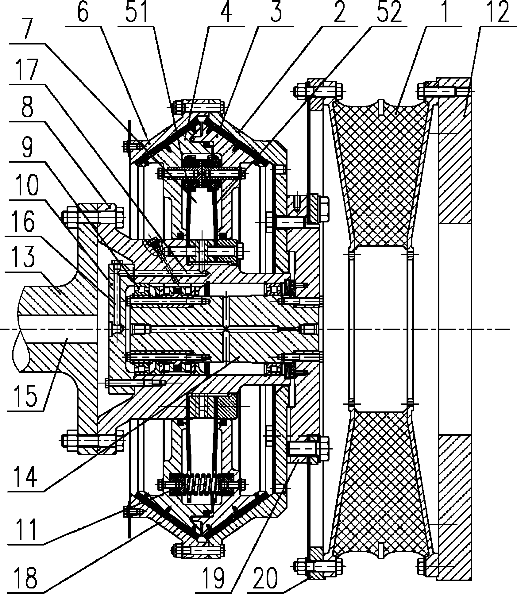
[0024] A marine clutch, including a clutch body 18, the clutch body 18 includes a first active friction cone 2, a first driven friction cone 3, a second active friction cone 6, a second driven friction cone 4, a hub 8, Gas distribution plate 10, cover plate 19, transition plate 20, gas distribution plate 10 is provided with air channel 16, one side of clutch body 18 is connected with gearbox input shaft 13, the other side of clutch body 18 is connected with diesel engine flywheel 12, clutch body 18 is connected to the side of the diesel engine flywheel 12 and is also provided with a high elastic element 1 between the clutch body 18 and the diesel engine flywheel 12, between the first driven friction cone 3, the second driven friction cone 4, the hub 8 and the mandrel 14 The first diaphragm assembly 51 and the second diaphragm assembly 52 are arranged between them, and there...


PUM


Abstract

The invention discloses a marine clutch. The clutch comprises a clutch body, wherein the clutch body comprises a first driving friction cone, a first driven friction cone, a second driving friction cone, a second driven friction cone, a shaft hub, an air distribution disc, a cover plate and a transition disc, wherein an air channel is formed on the air distribution disc; one side of the clutch body is connected with a gear box input shaft, and the other side of the clutch body is connected with a diesel engine flywheel; the side of the clutch body, which is connected with the diesel engine flywheel, is provided with a high-elasticity element between the clutch body and the diesel engine flywheel; a first diaphragm component and a second diaphragm component are arranged between the first driven friction cone and the shaft hub, and between the second driven friction cone and a spindle respectively; a cylinder is arranged among the first driven friction cone, the second driven friction cone and the shaft hub; and a bearing part is arranged between the shaft hub and the spindle. The high-elasticity element for shock absorption is independently arranged outside the clutch and is connected in series with the clutch, so that the radial space of the high-elasticity element is unlimited and can be arbitrarily determined according to the requirement, and the shock absorption function of the high-elasticity element is fully exerted.

Description

technical field [0001] The invention relates to a marine clutch, which belongs to the output coupling device of large-scale marine power equipment. Background technique [0002] The high-elastic clutch in the power transmission system of the main engine of the ship usually adopts rubber elastic elements to be installed inside the driven friction cone of the clutch. When this structure is working, the rubber elastic elements often In the high temperature environment for a long time, the internal heat dissipation condition of the clutch is extremely poor, the rubber elastic elements are easy to age, and daily observation, maintenance and replacement are also very inconvenient. Failures such as hardening and damage of the rubber elastic elements cannot be found in time, which often leads to the abnormality of the clutch Clutch; the clutch with the rubber elastic element inside also has large radial and axial dimensions and heavy weight; the axial and radial compensation capabil...

Claims


Application Information

Patent Timeline
IPC IPC(8): F16D13/26F16D13/72F16D25/00F16F15/08
Inventor 何敏李伟张攀赵和军
Owner 无锡伏尔康科技有限公司
Learn More