
Method for eliminating error of cylinder screw thread non-contact measurement

A non-contact thread thread technology, applied in the direction of measuring devices, optical devices, instruments, etc., can solve the problems of thread tooth angle error and the inability to obtain the real parameters of thread tooth angle, etc.

Inactive Publication Date: 2011-10-19
NINGBO INST OF TECH ZHEJIANG UNIV ZHEJIANG
View PDF4 Cites 10 Cited by
  • Summary
  • Abstract
  • Description
  • Claims
  • Application Information

AI Technical Summary

Problems solved by technology

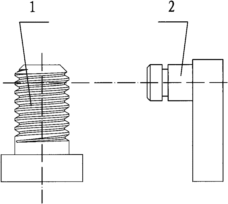
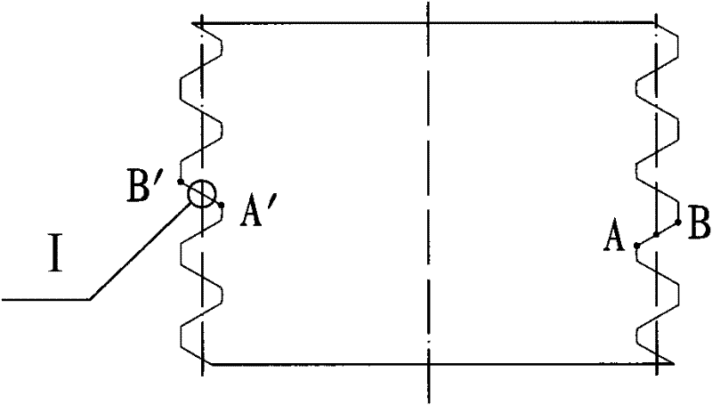
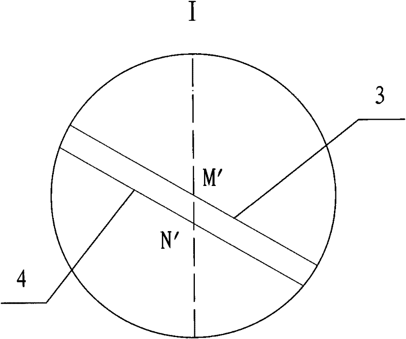
[0004] However, the above-mentioned non-contact measurement method based on a CCD camera has the following disadvantages: the cylindrical thread is truncated in half along its axis, figure 2 It is the view in the direction of the axial section, AB is a tooth profile intersection line of the cylindrical thread profile on the section, it is a real tooth profile line, but the thread of the bolt is in a helical state, and AB is according to the helix of the thread Rotate the thread for half a circle to get the helical surface, and form another tooth-shaped intersection line A'B' on the other side of the section. Set point M as a point on the intersection line AB, and point M is obtained after half a circle of rotation according to the spiral line of the thread. Point M' on the line of intersection A'B', such as image 3 shown in
However, this method also has errors: because the actual tooth shape is inclined by a thread angle φ, the thread image captured by the CCD camera is the projection of the actual tooth shape in the CCD camera lens. According to the projection relationship, the tooth shape of the projected tooth shape The profile angle must be smaller than the real tooth profile angle, and the projected pitch p' must also be smaller than the real pitch p
Therefore, this method cannot obtain the real parameters of the thread profile angle
[0006] In summary, there are errors between the thread profile angle displayed by the image captured by the CCD camera and the real thread profile angle

Method used


Image

  • Method for eliminating error of cylinder screw thread non-contact measurement
  • Method for eliminating error of cylinder screw thread non-contact measurement
  • Method for eliminating error of cylinder screw thread non-contact measurement

Examples


Embodiment Construction

[0051] The present invention will be further described in detail below in conjunction with the accompanying drawings and specific embodiments.

[0052] attached by Figure 8 Shown the present invention is used for eliminating the schematic flow chart of the method for non-contact measuring cylindrical thread profile error as known, it comprises the following steps:

[0053] (1) Propose the concept of projection boundary

[0054] The cross-sectional profile of the thread obtained after cutting along the axis of the bolt, AB is a tooth-shaped intersection line of the cylindrical thread profile on the cross-section, such as Figure 5 , Figure 6 and Figure 7 As shown, after AB rotates half a circle according to the helix of the thread, the helicoid is obtained, and another tooth-type intersection line A'B' is formed on the other side of the section. There is a point M on the intersection line AB, which reaches the central axis of the thread The distance is r, the point M rot...


PUM


Abstract

The invention discloses a method for eliminating error of cylinder screw thread non-contact measurement. The method comprises the following steps: presenting a concept of projection boundary, establishing projection boundary equation, obtaining difference relation of screw thread intersection line and projection boundary and correcting cylinder screw thread parameter. By employing the above method, spatial position relation is formed according to the screw thread projection boundary, the projection boundary equation is creatively established, the difference relation of the screw thread intersection line and the projection boundary is deduced on the former base, and extracted coordinates of points on cylinder screw thread image shot by a CCD camera are repeatedly corrected until the obtaining of cylinder screw thread parameter which satisfies precision requirement. The method is concise, visual, easy to grasp and easy to realize automatic detection. The non-contact detection method can avoid measurement error of high precision cylinder screw thread, and eradicate screw thread product quality problem caused by screw thread non-contact detection error.

Description

technical field [0001] The invention belongs to the field of mechanical detection, in particular to a detection method of mechanical parts, in particular to a method for eliminating non-contact measurement of cylindrical thread profile error. Background technique [0002] Bolts are very common standard parts in machinery and equipment. Qualified bolts are the basis for ensuring the reliable operation of the entire equipment. Therefore, the detection of threads is of great significance. Thread measurement usually adopts contact measurement methods, such as thread micrometer measurement, three-needle method, etc. However, these methods have problems such as low efficiency, low precision, high false detection rate, and high technical requirements for operators, which cannot meet the requirements of automatic detection. [0003] With the development of digital image processing technology, especially the advancement of image processing algorithms, the application of non-contact ...

Claims


Application Information

Patent Timeline
IPC IPC(8): G01B11/24G01B11/02G01B11/26
Inventor 陈俊华王贤成沈绍锋
Owner NINGBO INST OF TECH ZHEJIANG UNIV ZHEJIANG
Learn More