Method, device and system for controlling engineering machinery gear shifting

A technology for construction machinery and control devices, applied in control devices, mechanical equipment, transmission control, etc., can solve problems such as gearbox shocks, and achieve the effects of reducing torque shocks, improving operating comfort, and prolonging service life.

Inactive Publication Date: 2011-10-26
SANY HEAVY IND CO LTD (CN)
View PDF5 Cites 12 Cited by
  • Summary
  • Abstract
  • Description
  • Claims
  • Application Information

AI Technical Summary

Problems solved by technology

[0006] The main purpose of the present invention is to provide a control method, device and control system for gear shifting of construction machinery,

Method used


Image

  • Method, device and system for controlling engineering machinery gear shifting
  • Method, device and system for controlling engineering machinery gear shifting
  • Method, device and system for controlling engineering machinery gear shifting

Examples


Embodiment Construction

[0031] It should be noted that, in the case of no conflict, the embodiments in the present application and the features in the embodiments can be combined with each other. The present invention will be described in detail below with reference to the accompanying drawings and examples.

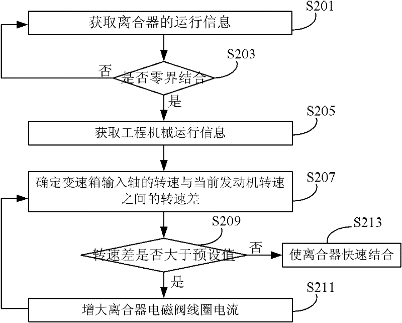
[0032] The technical solution of this embodiment can be used for the control of shifting gears of construction machinery. When the clutch zero boundary of construction machinery is combined, the speed difference between the gearbox input shaft and the engine is determined, and then the speed difference is compared with the preset value. If If the rotational speed difference is greater than the preset value, the coil current of the clutch solenoid valve is increased, so that the clutch is further combined. The technical solutions of the embodiments of the present invention are described in detail below.

[0033] figure 2 It is a flow chart of the main steps of the control method for gear shif...


PUM


Abstract

The invention provides a method, device and system for controlling engineering machinery gear shifting, wherein the method, device and system provided by the invention are used for solving the problem that the speed change box is subjected to greater impact caused by the clutch combination control method of mechanical land leveler in the prior art. The method comprises the following steps: determining the rotation speed difference between a speed change box input shaft and an engine when a clutch of engineering machinery is subjected to zero zone combination; and comparing the rotation speed difference with a preset value, and increasing the current of a clutch electromagnetic valve coil when the rotation speed difference is greater than the preset value, thus the clutch is combined further. By adopting the technical scheme provided by the invention, shock-less gear shifting can be realized, and the components of the speed change box are protected effectively; the torque impact of the clutch is released, and the service life is prolonged; and the working intensity of a driver is relieved, and the operation comfort is improved.

Description

technical field [0001] The invention relates to a control method, device and control system for gear shifting of engineering machinery. Background technique [0002] Mechanical grader is a widely used engineering machinery, the basic structure of its transmission system is shown in Figure 1. Figure 1A It is a schematic diagram of the basic structure of the mechanical grader transmission system related to the present invention. Figure 1A Among them, 11 is a front steering wheel, 19 is a rear driving wheel, 12 is a blade, 13 is a cab, 14 is a gear handle, 15 is a controller, 16 is an engine, and 17 is a gearbox. [0003] The power of the mechanical grader is output by the engine 16 and transmitted to the rear drive wheels 19 through the electro-hydraulic control gearbox 17 and the rear axle reduction mechanism. The gears of the transmission are in the state of constant mesh and rigid connection, and the shifting is completed by the electro-hydraulic control clutch. Figure ...

Claims


Application Information

Patent Timeline
IPC IPC(8): F16H61/04F16H61/02F16H59/02B60K20/02
CPCE02F3/7636E02F9/202F16H59/44F16H61/0213F16H2061/0216
Inventor 周风华王海涛李航洋
Owner SANY HEAVY IND CO LTD (CN)
Why Eureka
Try Eureka