Generator assembly for a wind power plant

A technology for wind energy equipment and generators, applied in wind energy power generation, wind turbine components, electromechanical devices, etc., can solve the problems of wear, complex mutual support of transmission components and generator components, etc., to shorten the path of the force line and simplify assembly. and the effect of disassembly

Inactive Publication Date: 2012-10-24
ROBERT BOSCH GMBH
View PDF9 Cites 0 Cited by
  • Summary
  • Abstract
  • Description
  • Claims
  • Application Information

AI Technical Summary

Problems solved by technology

However, these solutions have the disadvantage of the complex mutual support of the individual transmission and generator components
The tolerances to be followed during production are therefore relatively small, since several components move relative to one another in the assembled state, which rapidly leads to wear in the case of excessive play

Method used


Image

  • Generator assembly for a wind power plant
  • Generator assembly for a wind power plant
  • Generator assembly for a wind power plant

Examples


Embodiment Construction

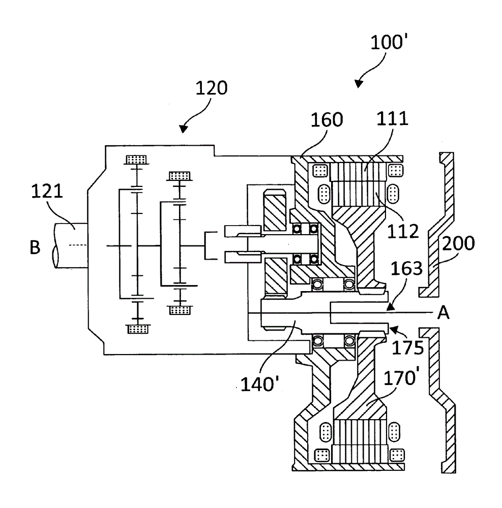
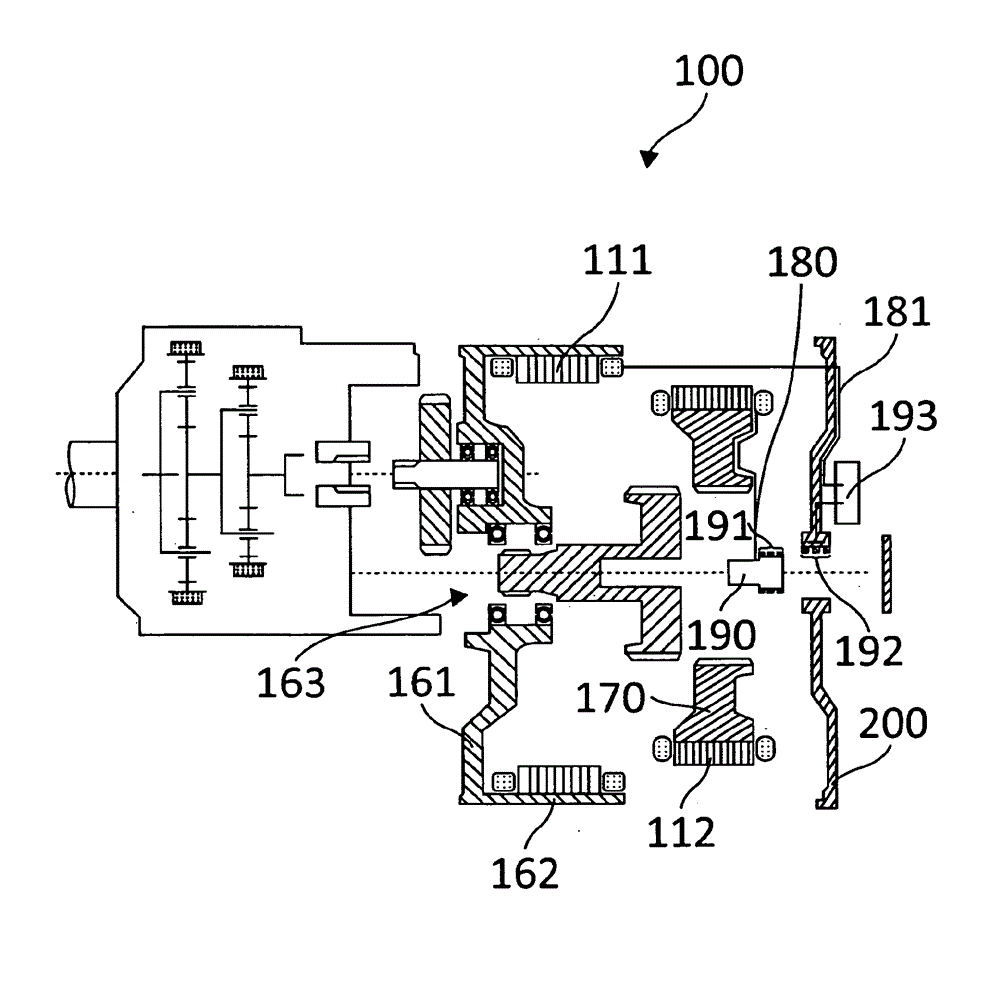
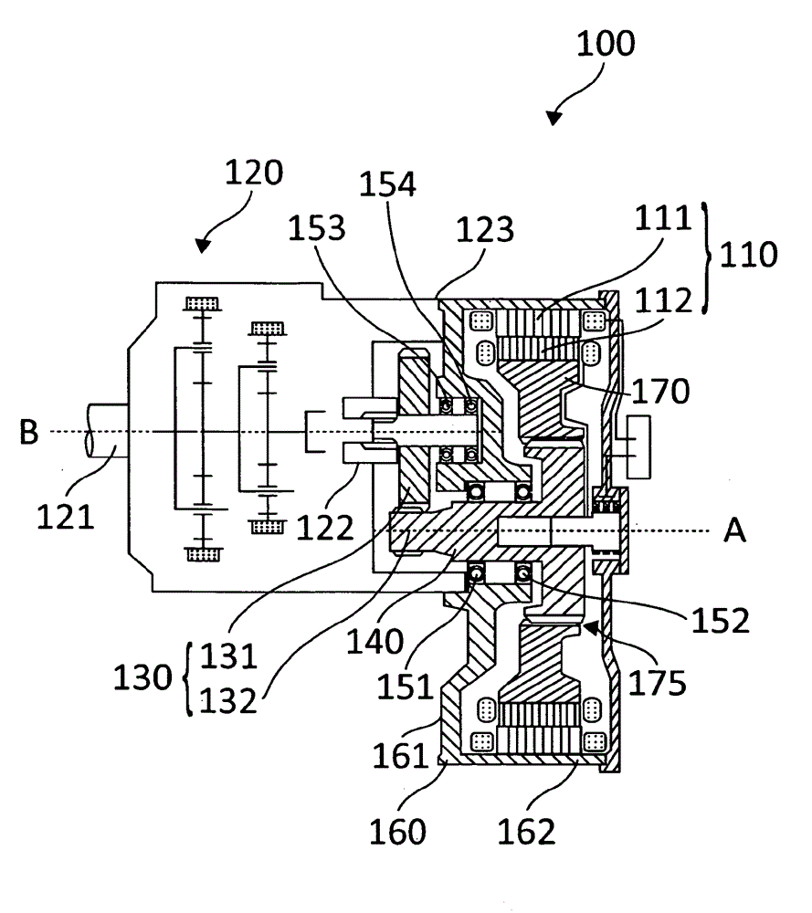
[0021] on the one hand figure 1 and figure 2 and on the other hand in image 3 Various embodiments of the generator arrangement according to the invention are shown in the figure, but these are described below mainly to the extent that they contain identical or identically acting elements. These elements are provided with the same reference numerals.

[0022] exist figure 1 and figure 2 In , a first preferred embodiment of the generator arrangement according to the invention is shown schematically in cross-section and is indicated overall by 100 . The generator arrangement 100 comprises a doubly-fed asynchronous generator 110 with a stator 111 containing a coil arrangement and a rotor 112 containing a coil arrangement, the winding ends of which are also drawn beside each other on the right and left . The rotor 112 is mounted rotatably about an axis A of rotation.

[0023] The generator arrangement has a base frame component 160 which at the same time serves as a housi...


PUM


Abstract

The invention relates to a generator assembly for a wind power plant having an annular stator, an annular rotor and a spur gear transmission assembly, wherein the generator assembly has a basic carrier component on which all the bearings of the generator assembly are arranged.

Description

technical field [0001] The invention relates to a generator arrangement for a wind energy installation. Background technique [0002] Most known wind power installations or wind energy installations are equipped with fast-rotating generators, in which single-stage or multi-stage transmissions are used to convert the relatively slow rotational speed of the wind rotor into the generator rotational speed. Solutions are known in which the transmission and the generator are arranged consecutively as separate components on the machine frame. This enables simple replacement of components in the event of damage, but the entire arrangement is relatively large and heavy, which causes problems in transporting the nacelle and the arrangement of the wind energy installation. [0003] Furthermore, arrangements are known in which the transmission is arranged at least partially within the generator, which results in a space saving. Exemplary solutions are disclosed in DE 102 42 703 B3 or ...

Claims


Application Information

Patent Timeline
Patent Type & Authority Applications(China)
IPC IPC(8): H02K7/18F16H37/04
CPCF05B2260/4031Y02E10/725Y02E10/722F05B2240/21H02K7/1838F03D11/02H02K7/116F03D15/00Y02E10/72F16H37/041F03D15/10F03D80/70
Inventor A.帕韦莱茨H-J.滕贝格
Owner ROBERT BOSCH GMBH
Why Eureka
Try Eureka