
Simulated deepwater oil-gas-water mixed transportation experimental device

A technology of experimental device and simulation device, which is applied in gas/liquid distribution and storage, pipeline system, mechanical equipment, etc. It can solve various tasks that are not satisfied with the actual working conditions of high pressure and low temperature in deep water, difficult to promote deep water engineering, and cannot simulate safety problems. condition, etc.

Active Publication Date: 2011-10-26
CHINA NAT OFFSHORE OIL CORP +2
View PDF5 Cites 32 Cited by
  • Summary
  • Abstract
  • Description
  • Claims
  • Application Information

AI Technical Summary

Problems solved by technology

[0008] (1) The function of the laboratory loop is single, and it cannot simulate various working conditions of deep water flow security issues;
[0009] (2) The current laboratory loop is mainly focused on the research of medium and low pressure systems, which is not satisfied with the actual working conditions of deep water, high pressure and low temperature;
[0010] (3) At present, the research on deep-water flow security technology in my country is not deep enough, and the design scale and test methods of related multi-phase mixed transmission loops are far from the actual working conditions of deep water, and the experimental results are difficult to be extended to deep-water engineering applications

Method used


Image

  • Simulated deepwater oil-gas-water mixed transportation experimental device
  • Simulated deepwater oil-gas-water mixed transportation experimental device

Examples


Embodiment Construction

[0027] The present invention will be further described below in conjunction with the examples, but the present invention is not limited to the following examples.

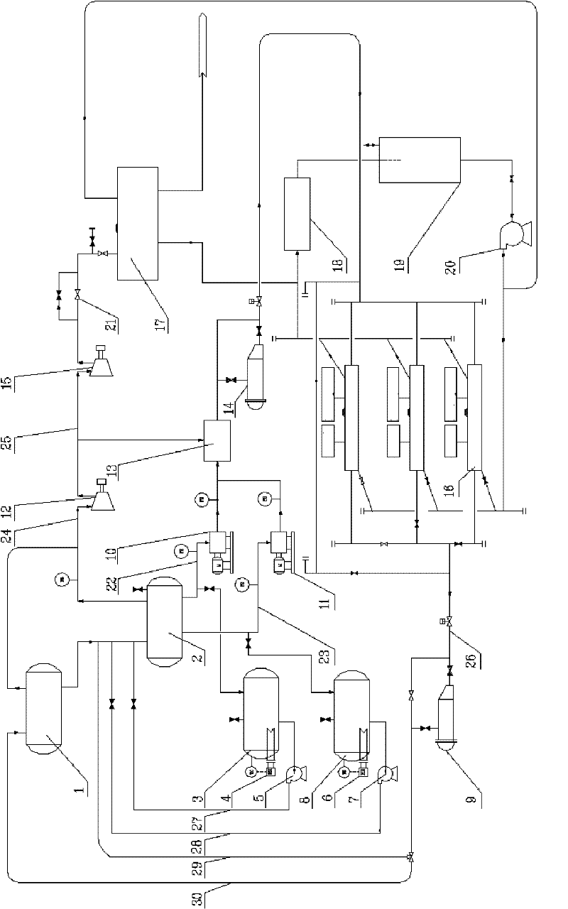
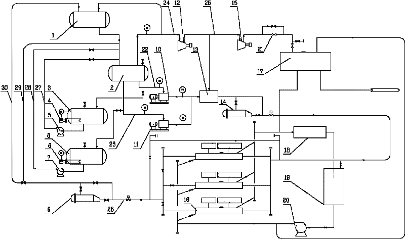
[0028]The oil-gas-water mixed transportation experimental device of the present invention comprises a gas-liquid two-phase separator 1, an oil-gas-water three-phase separator 2, an oil storage tank 3, a water storage tank 8, an oil-gas-water three-phase mixer 13, a primary compressor 12, A secondary compressor 15, a natural gas hydrate generation simulation device and a jacketed tube heat exchange device; the oil storage tank 3 and the water storage tank 8 are respectively equipped with an oil storage tank heater 4 and a water storage tank heater 6; the oil storage tank 3 and the water storage tank 8 communicate with the oil-gas-water three-phase separator 2 through the horizontal pipeline I 27 and the horizontal pipeline II 28 respectively, and the horizontal pipeline I 27 and the horizontal pipeline II 28 are resp...


PUM


Abstract

The invention provides a simulated deepwater oil-gas-water mixed transportation experimental device. The experimental loop comprises a slug flow catcher, an oil-gas-water three phase separator, an oil storage tank, a water storage tank, an oil-gas-water three phase mixer, a first stage compressor, a second stage compressor, a natural gas hydrate generation simulation device and a pinch-sleeve type heat-exchange device, wherein the oil storage tank and the water storage tank are respectively communicated with the oil-gas-water three phase separator through a horizontal pipeline I and a horizontal pipeline II; the oil outlet, the water outlet and the gas outlet of oil-gas-water three phase separator are respectively connected with the oil-gas-water three phase mixer through a pipeline a, a pipeline b and a pipeline c; an oil transfer pump, a water transfer pump and the first stage compressor are respectively arranged on the pipeline a, the pipeline b and the pipeline c; the first stage compressor is connected with the second stage compressor through a pipeline d; the second stage compressor is connected with the natural gas hydrate generation simulation device; the outlet of the oil-gas-water three phase mixer is connected with a tilting pipeline e, and the other end of the pipeline e is connected with the inlet of a stand pipe; a visual window is arranged on the pipeline e; andan exit end of the stand pipe is connected with the slug flow catcher.

Description

technical field [0001] The invention relates to an experimental device for simulating mixed transport of oil, gas and water in deep water, and belongs to the technical field of deep water flow safety assurance. Background technique [0002] Compared with single-phase flow, oil-gas-water multiphase flow is a very complicated flow. It can be said that so far people still haven't fundamentally solved the problem of accurately predicting its flow characteristics. Since the late 1970s, the discovery and development of North Sea oilfields in Europe has gradually expanded, further increasing the demand for deep-water multiphase mixed transportation technology, and effectively promoting the development of this technology. [0003] The deep water seabed is a high static pressure and low temperature environment, which puts forward strict requirements on the submarine oil and gas mixed transportation pipeline. Field application practice in deepwater oil and gas fields shows that in d...

Claims


Application Information

Patent Timeline
Patent Type & Authority Applications(China)
IPC IPC(8): F17D1/00
Inventor 刘培林张姝妍李清平倪浩叶忠志鞠文杰杨宇航张佃臣韩旭平姚海元
Owner CHINA NAT OFFSHORE OIL CORP
Learn More