Solar workstation

A technology of solar energy and workstations, applied in the direction of solar thermal energy, solar thermal installations, renewable energy integration, etc., can solve the problems of unreasonable space layout and large volume of solar workstations, and achieve the effect of compact structure, small volume and reasonable space layout

Inactive Publication Date: 2013-04-17
GRUNDFOS MANAGEMENT AS
View PDF7 Cites 0 Cited by
  • Summary
  • Abstract
  • Description
  • Claims
  • Application Information

AI Technical Summary

Problems solved by technology

[0006] The purpose of the present invention is to solve the technical problems of unreasonable spatial layout and large volume of existing solar workstations

Method used


Image

  • Solar workstation
  • Solar workstation
  • Solar workstation

Examples


Embodiment 1

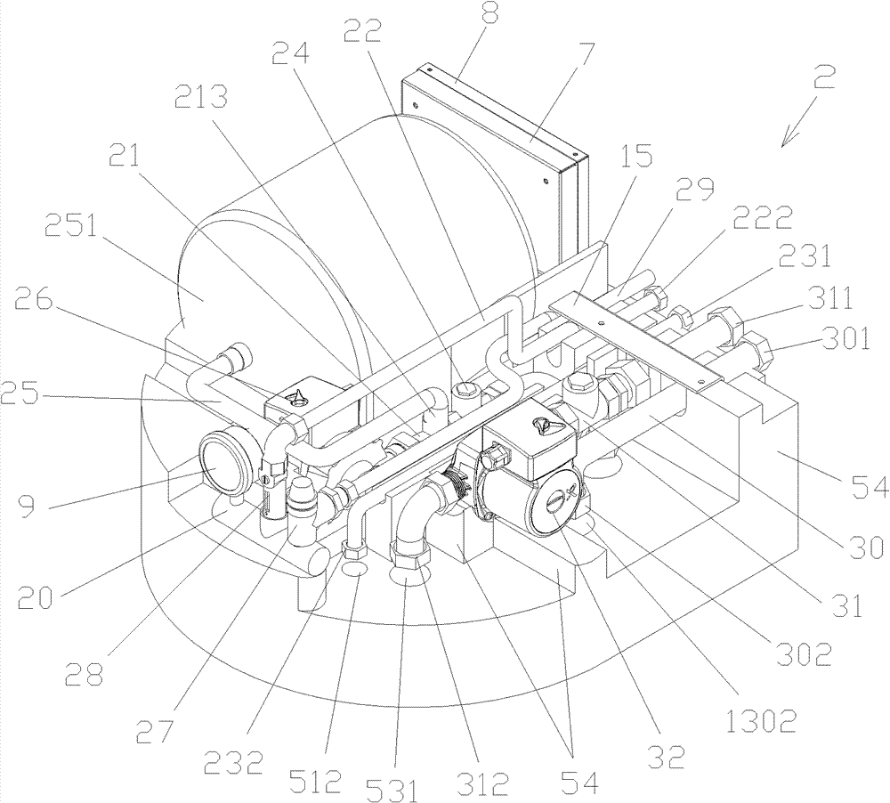
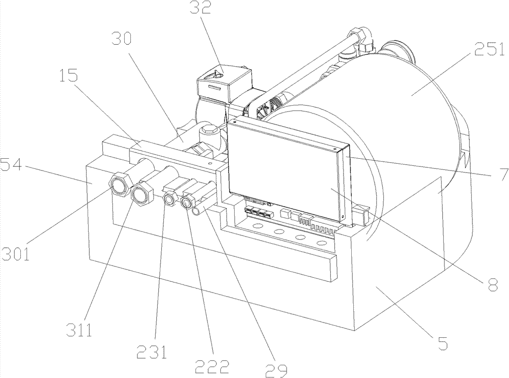
[0040] Such as figure 1 , figure 2 with image 3 As shown, the solar workstation in Embodiment 1 includes a thermal insulation base 5 , a controller 8 and a medium circulation system 2 .

[0041] The medium circulation system 2 includes a four-way joint 20, a first medium pipeline, a second medium pipeline 23, a buffer pipeline 25, a pressure relief pipeline 29, a one-way valve 24, an expansion tank 251, a medium pump 26, and a safety valve 27 , Flow meter 28 and pressure gauge 9 etc.

[0042] The first medium pipeline includes a first medium liquid inlet pipeline 21 and a first medium liquid return pipeline 22 .

[0043] The first medium liquid inlet pipeline 21 is horizontally installed on the heat preservation base 5 along the front and rear direction of the heat preservation base 5, and the inlet end of the first medium liquid inlet pipeline 21 is equipped with a connection port, and the connection port can be a connecting elbow, and the outlet The end communicates wi...

Embodiment 2

[0053] The parts of the solar workstation in Embodiment 2 that have the same structure as Embodiment 1 will not be repeated here. The difference between the solar workstation of this embodiment 2 and the foregoing embodiment 1 is that a hot water return pipe 30 installed in parallel with the first medium liquid inlet pipeline 21 is added in the medium circulation system, and the hot water return pipe 30 One end of one end stretches out the rear end face of heat preservation base 5, and is equipped with connection port 301, and the connection port of the other end is connection elbow 302. The protruding end of the hot water return pipe 30 is located on the same plane as the protruding ends of the first medium return pipeline 22 , the second medium pipeline 23 and the pressure relief pipeline 29 .

[0054] Correspondingly, the front side of the heat preservation base 5 is also provided with an accommodating tank for fixing the hot water return pipe 30, and the heat preservation ...

Embodiment 3

[0057] The parts of the solar workstation in Embodiment 3 that have the same structure as Embodiment 2 will not be repeated here. The difference between the solar workstation of this embodiment 3 and the foregoing embodiment 2 is that: a hot water inlet pipe 31 installed in parallel with the first medium liquid inlet pipeline 21 is added to the medium circulation system, and a hot water inlet pipe 31 installed in the hot water inlet pipe Water pump 32 on 31, one end of this hot water inlet pipe 31 stretches out the rear end face of heat preservation base 5, and connection port 311 is installed, and the connection port of the other end is connection elbow 312. The extension end of the hot water inlet pipe 31 and the extension end of the hot water return pipe 30, the extension end of the first medium return line 22, the extension end of the second medium line 23 and the pressure relief line 29 are located at on the same plane.

[0058] Correspondingly, the front of the heat pre...


PUM


Abstract

The invention provides a solar workstation for the solar energy heating system, wherein the solar energy heating system comprises a controller, a medium circulating system and a thermal insulation base. A bottom shape of the thermal insulation base matches the top shape of the thermal insulation water tank in the solar energy heating system. Various pipelines of the medium circulating system are parallel to each other and are installed on the thermal insulation base horizontally. One end of each of the first medium pipeline, the second medium pipeline and the pressure-release pipeline protrudes to the rear end surface of the thermal insulation base. A through hole is provided on the thermal insulation base at positions corresponding to the other ends of the first medium pipeline and the second medium pipeline. The solar workstation according to the invention has a compact structure, a smaller volume and an appropriate spatial arrangement. The solar workstation according to the present invention can be placed on the thermal insulation base flat, and fully utilizes the space above the thermal insulation water tank. Therefore, the solar energy heating system equipped with the solar workstation according to the invention has an appropriate overall arrangement.

Description

technical field [0001] The invention relates to a solar workstation for a solar heating system. Background technique [0002] The solar heating system includes thermal water tanks, collectors, heat exchangers and solar workstations. Among them, the heat preservation water tank is used to hold water and can be placed indoors; the heat collector needs to be installed in a place where the outdoor sun can shine, and it is used to absorb the heat energy of the sun; the heat exchanger is usually set in the water tank, and the solar workstation is connected to the heat exchange Between the collector and the collector. [0003] A traditional solar workstation includes a housing, a controller and a medium circulation system. The medium circulation system includes a medium circulation pipeline, a pressure relief pipeline and a buffer pipeline respectively connected with the medium circulation pipeline, an expansion tank installed on the buffer pipeline, a safety valve installed on t...

Claims


Application Information

Patent Timeline
Patent Type & Authority Patents(China)
IPC IPC(8): F24J2/46
CPCF24D11/003F24D19/0097F24D2200/14F24D2220/025F24D2220/0278F24D2220/06F24D2220/08Y02B10/20
Inventor 林欢喜罗伯特·格列韦赵学琴袁磊
Owner GRUNDFOS MANAGEMENT AS
Why Eureka
Try Eureka