CO2 laser tube

A technology of laser tube and tube body, applied in the field of CO2 laser tube, can solve the problem of unstable lens angle, and achieve the effect of improving spot quality, improving consistency and stability, and reducing dependence.

Inactive Publication Date: 2011-10-26
周迅
View PDF6 Cites 1 Cited by
  • Summary
  • Abstract
  • Description
  • Claims
  • Application Information

AI Technical Summary

Problems solved by technology

[0003] The purpose of the present invention is to solve the problems in the prior art, and propose a CO2 laser tube, which can effectively solve the problem of unstable lens angles under the working state of the laser tube, and greatly reduce the laser tube’s impact on the operating technicians during the production process. Dependence on skill proficiency improves the convenience of production and assembly

Method used


Image

  • CO2 laser tube
  • CO2 laser tube
  • CO2 laser tube

Examples


Embodiment 1

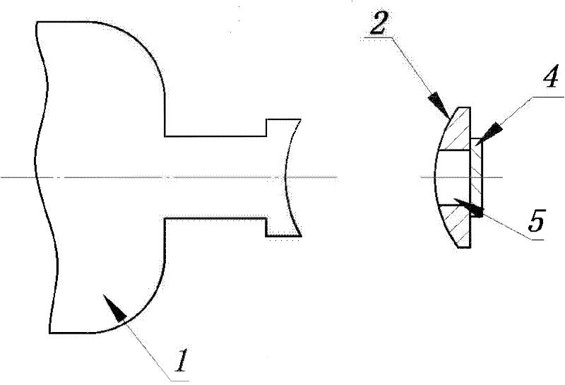
[0014] like figure 1 As shown, the CO2 laser tube includes a tube body 1 and a lens 4, and also includes a spherical mirror seat 2 and a light hole 5. The end face of the tube body 1 is mechanically or manually ground into a tube spherical surface, and the radius of the tube spherical surface is the same as that of the spherical mirror seat 2. The radius of the spherical surface is the same, and the concave and convex are opposite. The flat end of the spherical mirror base 2 is glued to the lens 4, and then glued together on the tube body 1. Due to the spherical contact, the direction can be adjusted arbitrarily, and it is very easy to adjust the angle of the spherical mirror base to drive the lens 4. It is perpendicular to the axis line of the pipe body 1. Since the end face of the pipe body can be selected and preferably mechanically ground, the problem of insufficient flatness of the original manual grinding is avoided. Because it is a spherical contact, any angle can be adj...

Embodiment 2

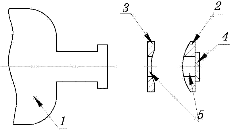
[0016] like figure 2 As shown, the CO2 laser tube includes a tube body 1 and a lens 4, and also includes a spherical mirror seat 2, a spherical connecting frame 3 and a light hole 5. The end face of the tube body 1 is ground into a plane by mechanical or manual methods, and the spherical connecting frame 3 One end of the plane is bonded to it, and the other side of the spherical connecting frame is a spherical surface, and its spherical radius is the same as that of the spherical mirror base 2, and the concave and convex are opposite. Also, due to the spherical contact, it can be adjusted at any angle so that the lens 4 is perpendicular to the axis of the tube body 1. Since the end surface of the tube body 1 can be mechanically ground, the spherical mirror seat 2 and the spherical connecting frame 3 are all made of a CNC lathe. Finished, it also avoids many problems in manual operation, greatly increases the laser output power, improves the quality of the spot, reduces the de...

Embodiment 3

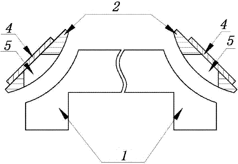
[0018] like image 3 As shown, the present embodiment is used for a folded CO2 laser tube, including a tube body 1 of a folded CO2 laser tube, a lens 4, a spherical mirror seat 2, and an optical hole 5, and the two parts of the tube body 1 of a folded CO2 laser tube Two ports are ground into a spherical surface, the radius of the spherical surface is the same as that of the spherical mirror base, and the concave and convex are opposite. The spherical mirror base 2 is bonded to the lens 4, and then bonded to the tube body 1 together. Adjust the angles of the two spherical mirror bases arbitrarily, so that the folding CO2 The two axis lines of the laser tube are on the same straight line through the two lenses. Since the spherical contact can be adjusted at any angle, the difficulty of manual grinding is greatly reduced, and the consistency of production efficiency is greatly improved.


PUM


Abstract

The invention discloses a CO2 laser tube which comprises a tube body, a lens and a spherical lens seat. The spherical lens seat is provided with light through holes. One end of the spherical lens seat is plane and the other end is spherical surface. The lens is bonded on the plane of the spherical lens seat. The spherical surface of the spherical lens seat is connected with the tube body. In the invention, the spherical lens seat is connected with the tube body and the lens, which solve a problem of vertical precision between a transverse plane and an axial lead of the tube body, wherein the vertical precision problem exists in a handwork grinding process of a traditional technology. Therefore, dependence on technology workers can be substantially reduced and laser tube output power can be substantially raised. Light spot quality of output power can be improved. Consistency and stability of batch can be substantially raised. The spherical lens seat is provided with the light through holes, which does not influence resonance and light. The spherical lens seat can be processed and formed by CNC lathes. Costs are low and promotion values are large.

Description

【Technical field】 [0001] The invention relates to a CO2 laser tube. 【Background technique】 [0002] The traditional CO2 laser tube is usually directly bonded by the lens and the tube body. Since the lens is coated after grinding and polishing in the process of forming, its plane roughness is better, while the end surface of the glass or quartz glass tube body can only Grinding and forming by hand, the flatness is not enough, which causes the angle between the lens and the tube axis to slightly deviate from the required 90° during the bonding process or during the laser working process, resulting in insufficient stability of the laser power and spot mode. to the best condition. In addition, some CO2 laser tubes use screws to fine-tune the lens angle. Although it can increase the laser power and improve the spot pattern in the short term, its long-term stability is not enough. 【Content of invention】 [0003] The purpose of the present invention is to solve the problems in ...

Claims


Application Information

Patent Timeline
Patent Type & Authority Applications(China)
IPC IPC(8): H01S3/03
Inventor 周迅
Owner 周迅
Why Eureka
Try Eureka