Plastic piece punching and cutting die

A technology of plastic parts and dies, which is applied in the field of stamping dies, can solve the problems of glue overflow, poor processing accuracy, and high cutting pressure, and achieve the effects of high surface finish, long service life, and reduced punching force

Inactive Publication Date: 2011-11-02
厦门加新精密金属有限公司
View PDF5 Cites 10 Cited by
  • Summary
  • Abstract
  • Description
  • Claims
  • Application Information

AI Technical Summary

Problems solved by technology

[0002] As an emerging industry in the mobile phone industry chain, the mobile phone touch screen is the main accessory of the mobile phone. It contains rich circuits. It is made of multi-layer PET materials and OCA. After the circuit is printed and pasted, it needs to be die-cut to size. ,Because it contains rich printed circuits, the traditional process of ordinary die-cutting is to use laser die-cutting or etching die-cutting. Due to the poor processing accuracy and rough surface of laser die-cutting die or etching die-cutting die, it will cause irregular cutting edges, circuit crushing, and glue overflow. , glue pulling and dimensional instability
The commonly used punching equipment for plastic parts is realized by the cooperation of the punch and the die. The punching end of the die is flat and has no cutting edge. The cutting pressure is relatively high, which is easy to cause the plastic optical glue to be bonded. Spills, gums, crushes, and forms product that is dimensionally unstable

Method used


Image

  • Plastic piece punching and cutting die
  • Plastic piece punching and cutting die

Examples


Embodiment Construction

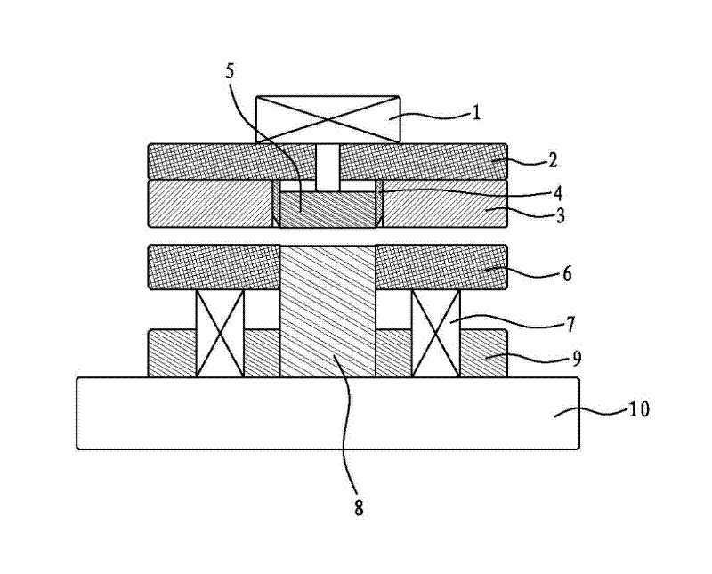
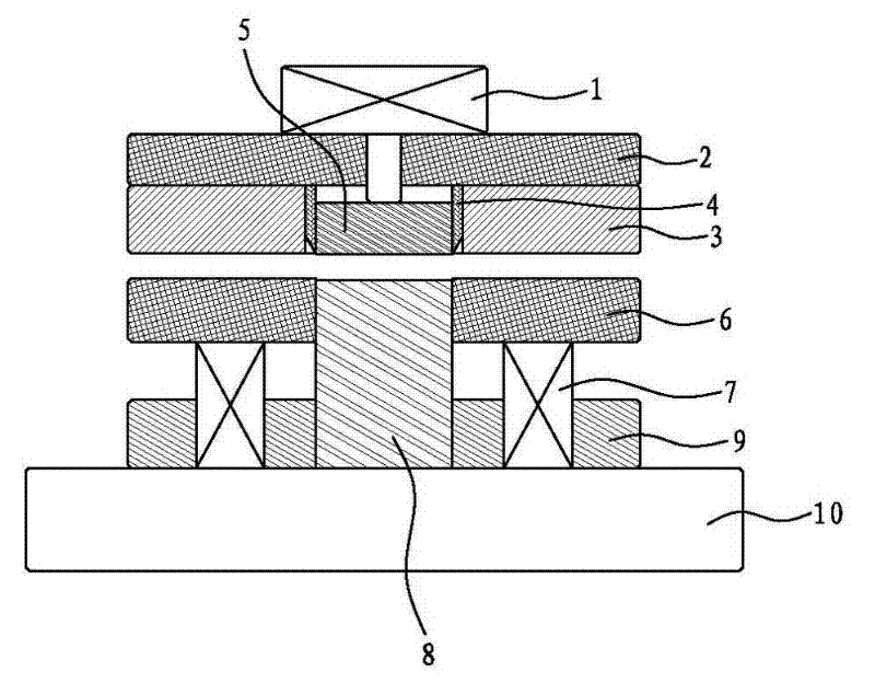
[0010] like figure 1 As shown, the present invention is a stamping and cutting die for plastic parts, which includes a cylinder 1, a upper die base plate 2, a upper die 3, a cutting die 4, a binder plate 5, a stripping plate 6, a stripping spring 7, a punch 8, lower mold 9, lower mold bottom plate 10.

[0011] The cylinder body of the cylinder 1 is installed on the outside of the upper die base plate 2, and the upper die 3 is fixed on the inner side of the upper die base plate 2; The surface of the die at the other end of the die 4 obliquely forms a cutting edge 41 inwardly, and the cutting edge is beveled.

[0012] The clamping plate 5 is movably nested in the cutting die 4; the piston rod of the cylinder 1 passes through the upper die bottom plate 2 through the connecting rod and presses on the clamping plate 5; the lower die 9 is fixed on the lower die. On the mold bottom plate 10. The stripping plate 6 is sleeved on the punch 8 at a gap, and the stripping spring 7 is se...


PUM


Abstract

The invention discloses a plastic piece punching and cutting die, which comprises a cylinder, an upper die base plate, an upper die, a cutting-off cavity die, a pressure plate, a stripping plate, stripping springs, a punching head, a lower die and a lower die base plate. One end of the cutting-off cavity die is fixed inside the upper die base plate and is sleeved inside the upper die; cutting edges are obliquely and inwards formed on the surfaces at another end of the cutting-off cavity die; the pressure plate is movably sleeved in the cutting-off cavity die; a piston rod of the cylinder penetrates through the upper die base plate and is supported and pressed on the stripping plate; the stripping plate is in clearance sleeve connection with the punching head; the stripping springs are arranged between the stripping plate and the lower die base plate; and the lower die is fixed on the lower die base plate. As the cutting edges are obliquely and inwards formed on the surfaces at another end of the cutting-off cavity die, the blanking force for punching and cutting a plastic piece by using the plastic piece punching and cutting die is greatly reduced, the occurrence of the phenomena of spillover, cement extrusion and crushing of optical cement used for bonding plastic during the process of punching is better avoided, and the size of punched and cut products is stable and accurate.

Description

technical field [0001] The invention relates to a stamping die, in particular to a stamping and cutting die for plastic parts. Background technique [0002] As an emerging industry in the mobile phone industry chain, the mobile phone touch screen is the main accessory of the mobile phone. It contains rich circuits. It is made of multi-layer PET materials and OCA. After the circuit is printed and pasted, it needs to be die-cut to size. ,Because it contains rich printed circuits, the traditional process of ordinary die-cutting is to use laser die-cutting or etching die-cutting. Due to the poor processing accuracy and rough surface of laser die-cutting die or etching die-cutting die, it will cause irregular cutting edges, circuit crushing, and glue overflow. , glue pulling and dimensional instability. The commonly used punching equipment for plastic parts is realized by the cooperation of the punch and the die. The punching end of the die is flat and has no cutting edge. The c...

Claims


Application Information

Patent Timeline
Patent Type & Authority Applications(China)
IPC IPC(8): B26F1/44
Inventor 王军
Owner 厦门加新精密金属有限公司
Why Eureka
Try Eureka