

Single-shaft steam turbine generator unit
A technology of steam turbine generator set and steam turbine generator, which is applied in the direction of steam generation, steam engine device, steam generation device, etc.
- Summary
- Abstract
- Description
- Claims
- Application Information
AI Technical Summary
Problems solved by technology
Method used
Image

Examples
no. 1 example
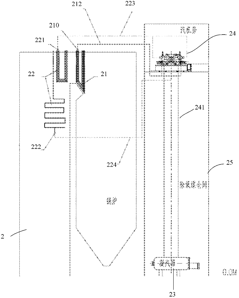
[0031] Such as figure 2 As shown, the single-shaft turbogenerator set in this example includes:
[0032] —— Boiler 2. Boiler 2 is a primary reheat boiler commonly used in this field, and its type is Π-type boiler or tower boiler ( figure 2 Shown is a Π-type boiler), the outside of the boiler is equipped with a deoxygenated coal bunker room 25, and the deoxygenated coal bunker room 25 is located in the turbine room, and the heating surface of the boiler 2 includes a superheater 21, a reheater 22 and a superheater outlet header 210. Reheat gas outlet header 221;
[0033] ——Steam turbine generator 24, including a steam turbine and a generator. The steam turbine is a once-reheated single-shaft condensing type wet-cooled steam turbine or a once-reheated single-shaft condensing type indirect air-cooled steam turbine commonly used in the field, including a high-pressure cylinder, a medium Pressure cylinder, two low-pressure cylinders; each cylinder of the steam turbine and the ge...
no. 2 example
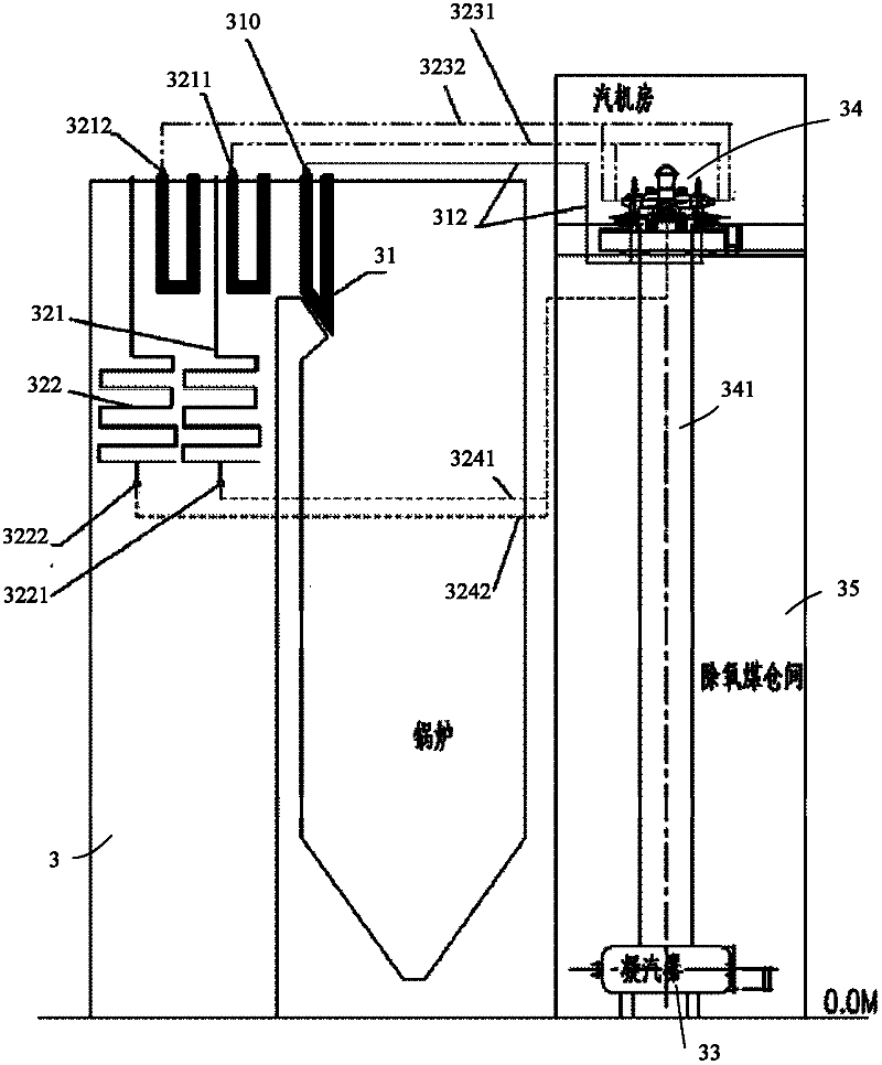
[0043] Such as image 3 The single-shaft turbo-generator set of the illustrated embodiment includes:
[0044] —— Boiler 3, boiler 3 is a secondary reheat boiler commonly used in this field, the type is Π-type boiler or tower boiler ( image 3 Shown is a Π-type boiler), the outside of the boiler is equipped with a deoxygenated coal bunker 35, and the deoxygenated coal bunker 35 is located in the turbine room; the heating surface of the boiler 3 includes a superheater 31, a primary reheater 321, and a secondary reheater 322, primary reheater outlet header 3211, secondary reheater outlet header 3212, superheater outlet header 210, primary reheater inlet header 3221, secondary reheater inlet header 3222;
[0045] ——The steam turbine generator 34, the steam turbine generator 34 includes a steam turbine and a generator, and the steam turbine is a double-reheated single-shaft condensing type wet-cooled steam turbine or a double-reheated single-shaft condensing type indirect air-cool...
no. 3 example
[0057] The single-shaft turbogenerator set in this example includes:
[0058] —— Boiler 4. Boiler 4 is a once-reheated boiler commonly used in this field, and its type is Π-type boiler or tower boiler ( Figure 4 Π-type boiler) or other types of boilers, the outside of the boiler is equipped with a deoxygenated coal bunker room 45, and the deoxygenated coal bunker room 45 is located in the turbine room; the heating surface of the boiler 4 includes a superheater 41, a reheater 42, a reheater Reheater inlet header 422, reheater outlet header 421, superheater outlet header 410;
[0059] ——Steam turbine generator 44, including a generator and a steam turbine, the steam turbine is a once-reheated single-shaft condensing steam direct air-cooled steam turbine commonly used in the field, including a high-pressure cylinder, a medium-pressure cylinder, and two low-pressure cylinders; each of the steam turbines Cylinder and generator are on the same shaft system;
[0060] ——The air-coo...
PUM
 Abstract
Description
Claims
Application Information