Optical fiber coupled connector

A fiber coupling and coupling connection technology, which is applied in the coupling direction of optical waveguide, can solve the problems of affecting the transmission efficiency of optical transmission devices, affecting the alignment degree and transmission efficiency of optical fibers, and affecting the coupling accuracy of optical fiber coupling connectors, etc., to achieve coupling accuracy The effect of improving and improving the uprightness and transmission efficiency

Inactive Publication Date: 2011-11-09
HONG FU JIN PRECISION IND (SHENZHEN) CO LTD +1
View PDF3 Cites 5 Cited by
  • Summary
  • Abstract
  • Description
  • Claims
  • Application Information

AI Technical Summary

Problems solved by technology

[0004] However, the above-mentioned fiber-optic coupling connector requires very high coupling accuracy between the lens in the fiber plug and the lens in the receptacle. If there is any error in production, assembly or use, it will seriously affect the fiber-optic coupling connector. Coupling precision, which in turn affects the transmission efficiency of the optical transmission device, and the fiber coupling connectors currently used generally use blind holes to accommodate and fix optical fibers, which requires good control of the diameter of the blind holes to avoid larger The diameter of the blind hole causes unstable displacement of the optical fiber in the blind hole, which affects the alignment and transmission efficiency of the optical fiber

Method used


Image

  • Optical fiber coupled connector
  • Optical fiber coupled connector
  • Optical fiber coupled connector

Examples


Embodiment Construction

[0035] The present invention will be described in further detail below in conjunction with the accompanying drawings.

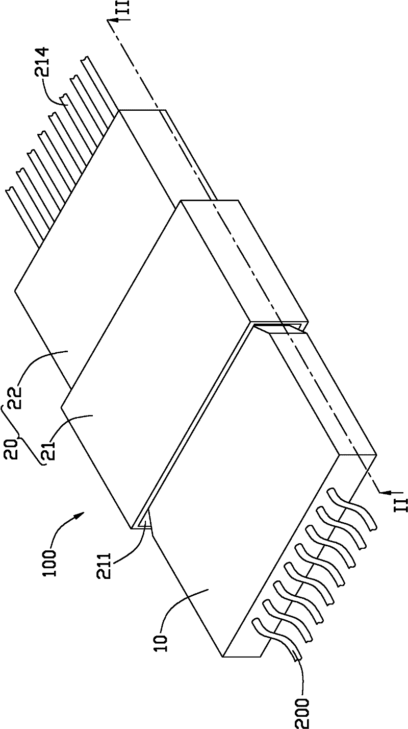
[0036] Please also see figure 1 and figure 2 , the fiber optic coupling connector 100 provided by the first embodiment of the present invention includes a fiber optic plug 10 and a receptacle 20, and the fiber optic plug 10 and the receptacle 20 cooperate with each other to realize signal transmission.

[0037] The optical fiber plug 10 has a substantially square housing 11 , and a plurality of through holes 12 arranged in parallel are opened on the housing 11 , and an optical fiber 200 is accommodated in each through hole 12 .

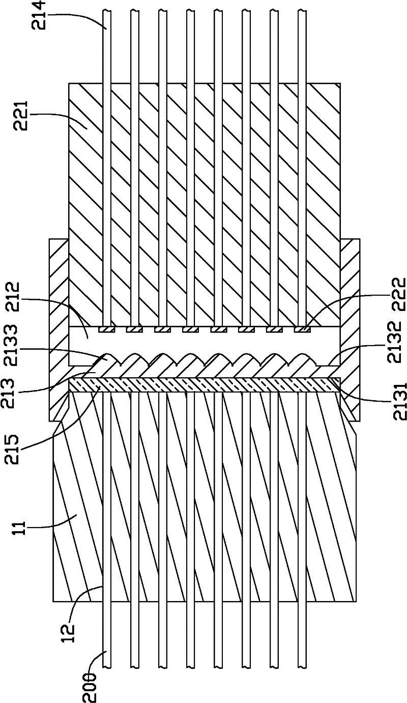
[0038] The socket 20 has a coupling portion 21 and a photoelectric signal conversion portion 22 . The optical fiber plug 10 is coupled and connected to the photoelectric signal converting portion 22 through the coupling portion 21 .

[0039] The coupling connection part 21 has a first slot 211 and a second slot 212, the first slo...


PUM


Abstract

The invention provides an optical fiber coupled connector. The connector comprises an optical fiber plug and a socket matched with the optical fiber plug, wherein the optical fiber plug is used for accommodating an optical fiber; an optical lens which is optically coupled with the optical fiber and a photoelectric signal converter are arranged at the socket end; and after an optical fiber signal enters the socket and is converged once through the optical lens, an optical signal is converted into an electric signal directly through the photoelectric signal converter for transmission. By the structure of combining the optical fiber plug and the socket with the structure, the coupling accuracy of the optical fiber coupled connector is greatly improved.

Description

technical field [0001] The invention relates to the field of Universal Serial Bus (USB), in particular to an optical fiber coupling connector. Background technique [0002] The USB data transmission technology has been widely used, and USB coupling connectors of different technical standards have different data transmission rates. The current mainstream USB2.0 products in the market have a transfer rate of about 500MB / Sec, and the transfer rate of the next-generation product USB3.0 reaches 3-5G / Sec. The transmission media of these two products are metal wire transmission. In order to meet higher transmission requirements, fiber-coupled connectors with higher data transmission rates have emerged. [0003] Existing optical fiber coupling connectors include optical fiber plugs and socket ends that cooperate with each other. Optical fibers and lenses coupled with the light are respectively arranged in the optical fiber plugs and socket ends. Optical signals are emitted from th...

Claims


Application Information

Patent Timeline
Patent Type & Authority Applications(China)
IPC IPC(8): G02B6/42
Inventor 林奕村
Owner HONG FU JIN PRECISION IND (SHENZHEN) CO LTD
Why Eureka
Try Eureka