Idle stroke-free punching machine

A stamping machine and idle stroke technology, which is applied in the field of no empty stroke stamping machine, can solve the problems of low work efficiency and large equipment investment, and achieve the effect of improving efficiency

Inactive Publication Date: 2011-11-16
王乃武
View PDF0 Cites 0 Cited by
  • Summary
  • Abstract
  • Description
  • Claims
  • Application Information

AI Technical Summary

Problems solved by technology

[0003] At present, in the product structure of domestic stamping machines, the stamping machine is composed of a slider. In this stamping machine structure, the slider completes a stamping process every time the crankshaft rotates. The stamping machine of this structure, Although it has the advantages of simple structure and good manufacturing process, the slider only completes the process task once in each cycle of the crankshaft, so there is a defect of low work efficiency. In addition, in some continuous process flows, in order to complete For two different processes, two or more stamping machines must be used to form a production line. Therefore, the current stamping machine still has the defect of large equipment investment in the continuous process flow.

Method used


Image

  • Idle stroke-free punching machine
  • Idle stroke-free punching machine
  • Idle stroke-free punching machine

Examples


Embodiment Construction

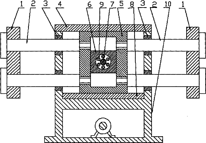
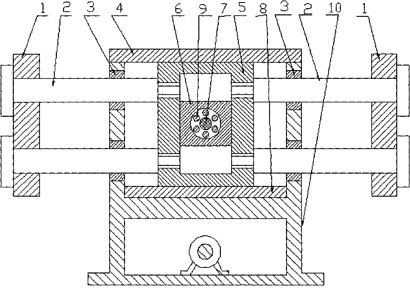
[0011] Install and fix the lower guide rail plate (8) at the ㄩ-shaped inner opening on the top of the fuselage (10), install the square sleeve (5) in the ㄩ-shaped opening on the lower guide rail plate (8), and pass the upper guide rail plate (4) through The bolts are installed and fixed on the upper opening of the ㄩ-shaped opening to ensure that the upper guide rail plate (4) and the lower guide rail plate (8) engage the square sleeve (5) in the ㄩ-shaped opening, so that the square sleeve (5) can only move left and right freely and ensure that the square sleeve (5) moves in the specified direction, install and fix the sliding bearing (3) on both sides of the ㄩ-shaped opening on the fuselage (10), and pass the guide rod (2) through the sliding bearing (3) Connect and fix the square sleeve (5), install and fix the slider (1) on the top of the guide rod (2), and install the square sleeve slider (6) at the mouth of the square sleeve (5) to ensure that the square sleeve slides The ...


PUM


Abstract

The invention relates to an idle stroke-free punching machine. An inverse n-shaped inner opening in a machine body is fixedly provided with a lower guide rail plate; a square sleeve is arranged in the inverse n-shaped opening in the lower guide rail plate; an upper guide rail plate is fixedly arranged on the upper opening of the inverse n-shaped opening through bolts; the square sleeve is clamped in the inverse n-shaped opening by using the upper guide rail plate and the lower guide rail plate to make the square sleeve only have the degree of freedom of left-to-right motion; the square sleeve is moved along a specified direction; sliding bearings are fixedly arranged on both sides of the inverse n-shaped opening in the machine body; guide rods pass through the sliding bearings and are fixedly connected with the square sleeve; sliding blocks are fixedly arranged at the top ends of the guide rods; a square sleeve sliding block is arranged at the opening in the center of the square sleeve to ensure that the square sleeve sliding block only has the degree of freedom of up-and-down motion in the opening of the square sleeve; a crank shaft is arranged on the upper side of the machine; a crank part of the crank shaft is arranged on the central part of the square sleeve sliding block through a bearing; one end of the crank shaft is fixedly provided with a clutch brake; and the clutch brake is connected with a transmission system.

Description

technical field [0001] The invention relates to a punching machine without an idle stroke, in particular to a punching machine without an idle stroke, and belongs to the technical field of forging equipment. Background technique [0002] The stamping machine is the main equipment in the forging production. It works through the periodic movement of the slider of the stamping machine and the stamping force generated by the slider to complete the specified process. [0003] At present, in the product structure of domestic stamping machines, the stamping machine is composed of a slider. In this stamping machine structure, the slider completes a stamping process every time the crankshaft rotates. The stamping machine of this structure, Although it has the advantages of simple structure and good manufacturing process, the slider only completes the process task once in each cycle of the crankshaft, so there is a defect of low work efficiency. In addition, in some continuous process...

Claims


Application Information

Patent Timeline
IPC IPC(8): B21J5/12B21J13/00
Inventor 王乃武
Owner 王乃武
Why Eureka
Try Eureka