Pressure device for locking mould

A pressure device and mold clamping technology, applied in the field of pressure devices, can solve the problems of difficult adjustment of mold clamping force, inability to adjust mold clamping force, difficulty in lubrication of mold clamping mechanism, etc., and achieve low manufacturing cost, fast boosting speed and long service life long effect

Inactive Publication Date: 2014-05-07
胡同庆
View PDF3 Cites 2 Cited by
  • Summary
  • Abstract
  • Description
  • Claims
  • Application Information

AI Technical Summary

Problems solved by technology

Because the clamping force is achieved through the elastic deformation of the system, the clamping force is not accurate, it is difficult to adjust the clamping force in different molding cycles, and the clamping force in the same molding cycle cannot be adjusted, and this mechanical clamping mechanism is relatively Difficult to lubricate, easily damaged, short service life

Method used


Image

  • Pressure device for locking mould
  • Pressure device for locking mould
  • Pressure device for locking mould

Examples


Embodiment Construction

[0021] The present invention will be further described in detail below in conjunction with the accompanying drawings and embodiments.

[0022] In this embodiment, an injection machine is taken as an example to illustrate the clamping pressure device.

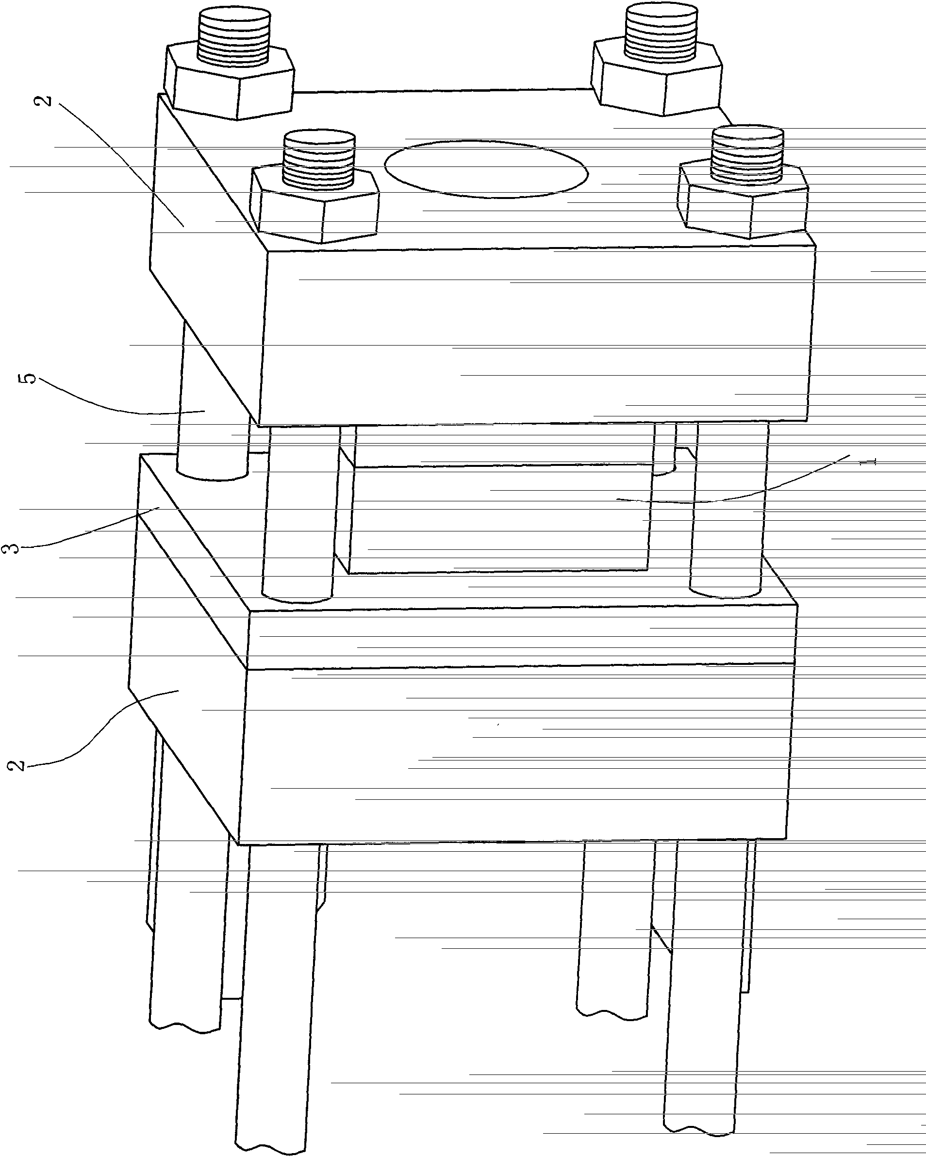
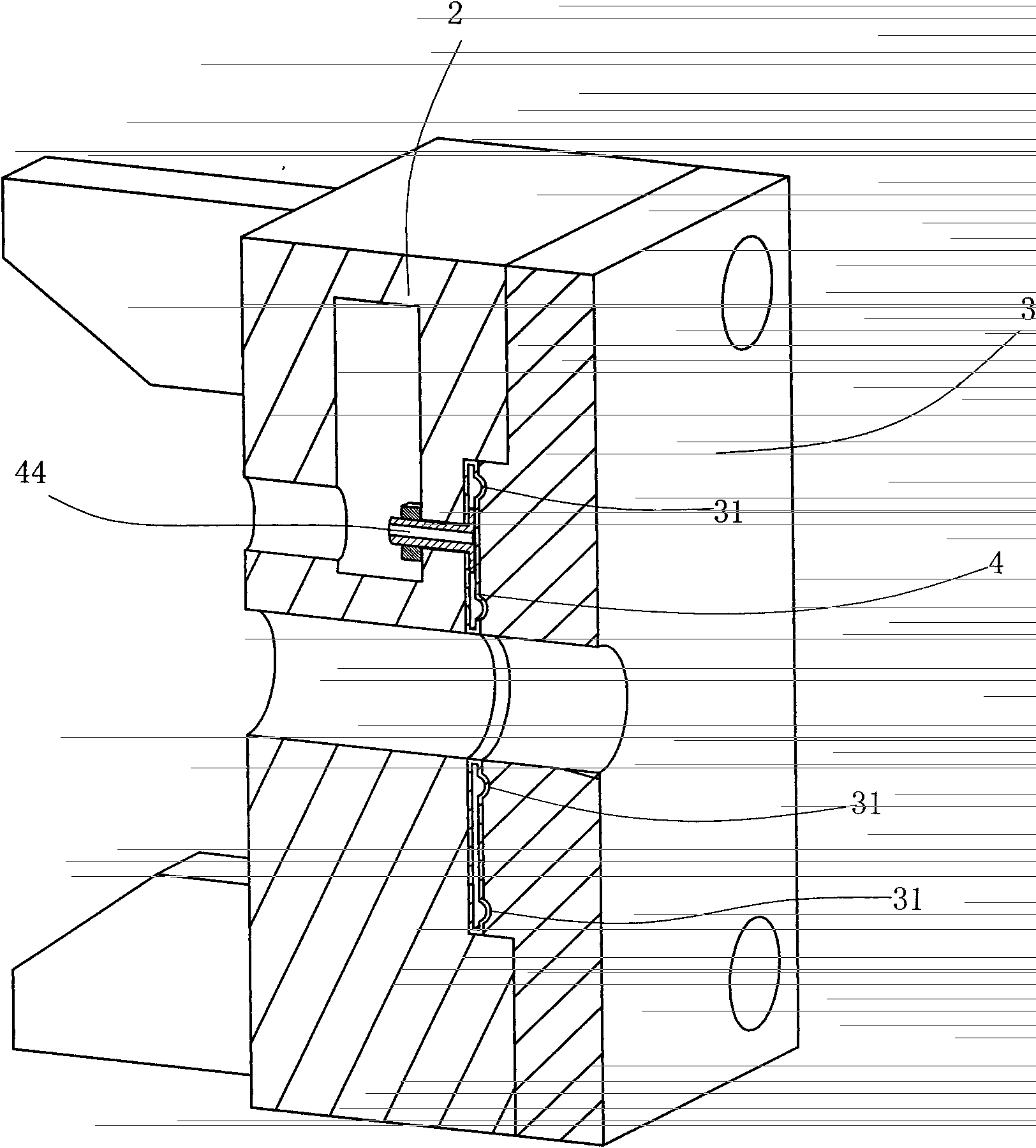
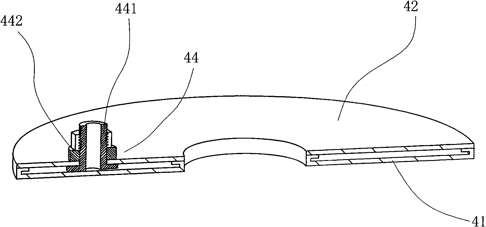
[0023] Such as Figure 1 to Figure 3 As shown, the clamping pressure device is set between the mold 1 and the template 2 of the clamping mechanism; in the prior art, the clamping mechanism includes three templates, one is a rear template, the other is a moving template, and the other is a fixed template. When working, the fixed template usually does not move, and the movable template moves back and forth. The pressure device provided in this embodiment can be set between the movable platen and the mold 1, or between the fixed platen and the mold. The fixed platen and the movable platen are collectively referred to as the platen. The pressure device in this embodiment includes:

[0024] The push plate 3 is arranged between the...


PUM

PropertyMeasurementUnit
heightaaaaaaaaaa
thicknessaaaaaaaaaa
depthaaaaaaaaaa

Abstract

The present invention relates to a pressure device for mould locking, which comprises a push plate arranged between a mould plate of a mould closing mechanism and a corresponding mould, wherein there is a gap between the push plate and the mould plate, in which gap a pressure bag is provided, the pressure bag being made from a resilient plastic cement and provided on a sidewall thereof with a metal interface to be connected with a hydraulic apparatus for feeding a pressure medium into the pressure bag. As compared to the prior art, the pressure device for mould locking provided in the present invention, used in cooperation with a mould closing mechanism on a related apparatus, overcomes defects of hydraulic mould closing mechanisms, such as complex structure, high cost, low efficiency and easy leakage of oil, as well as overcoming defects of crankshaft-type mould closing mechanisms, such as difficulty in control of mould locking forces, low precision, low wear resistance and short service lifetime.

Description

technical field [0001] The invention relates to a pressure device, in particular to a pressure device for mold clamping. Background technique [0002] In the field of industrial molding, processes such as plastic injection molding, metal die-casting, and other products that require molding or compaction need to be operated under a certain pressure, and clamping mechanisms are usually used to provide and maintain pressure for these processes. There are usually two types of mold clamping mechanisms currently in use, one is a fully hydraulic mold clamping mechanism, and the other is a toggle mechanical mold clamping mechanism. [0003] The fully hydraulic clamping mechanism pushes the moving platen through the oil cylinder installed on the machine platen, pushes the mold to the direction of the fixed platen to close the mold, and finally locks the mold by establishing the high pressure of the oil in the cylinder. Due to the great force to ensure that the mold is locked, the re...

Claims


Application Information

Patent Timeline
Patent Type & Authority Patents(China)
IPC IPC(8): B29C45/67
CPCB29C45/6778B29C45/6721B22D17/266
Inventor 陈国永
Owner 胡同庆
Why Eureka
Try Eureka