Cooling device for powder burned by saggar

A cooling device and powder technology, applied in inorganic chemistry, phosphorus compounds, non-metallic elements, etc., to achieve the effects of energy-saving powder cooling, simplified structure, and space saving

Inactive Publication Date: 2011-11-16
NGK INSULATORS LTD
View PDF2 Cites 7 Cited by
  • Summary
  • Abstract
  • Description
  • Claims
  • Application Information

AI Technical Summary

Problems solved by technology

[0004] Under such circumstances, there are unsatisfactory problems that a long and large powder cooling space for cooling the powder in a low-oxygen environment or a facility with a strong cooling capacity needs to be provided at the front stage of the powder recovery process. cooling device

Method used


Image

  • Cooling device for powder burned by saggar
  • Cooling device for powder burned by saggar
  • Cooling device for powder burned by saggar

Examples


Embodiment Construction

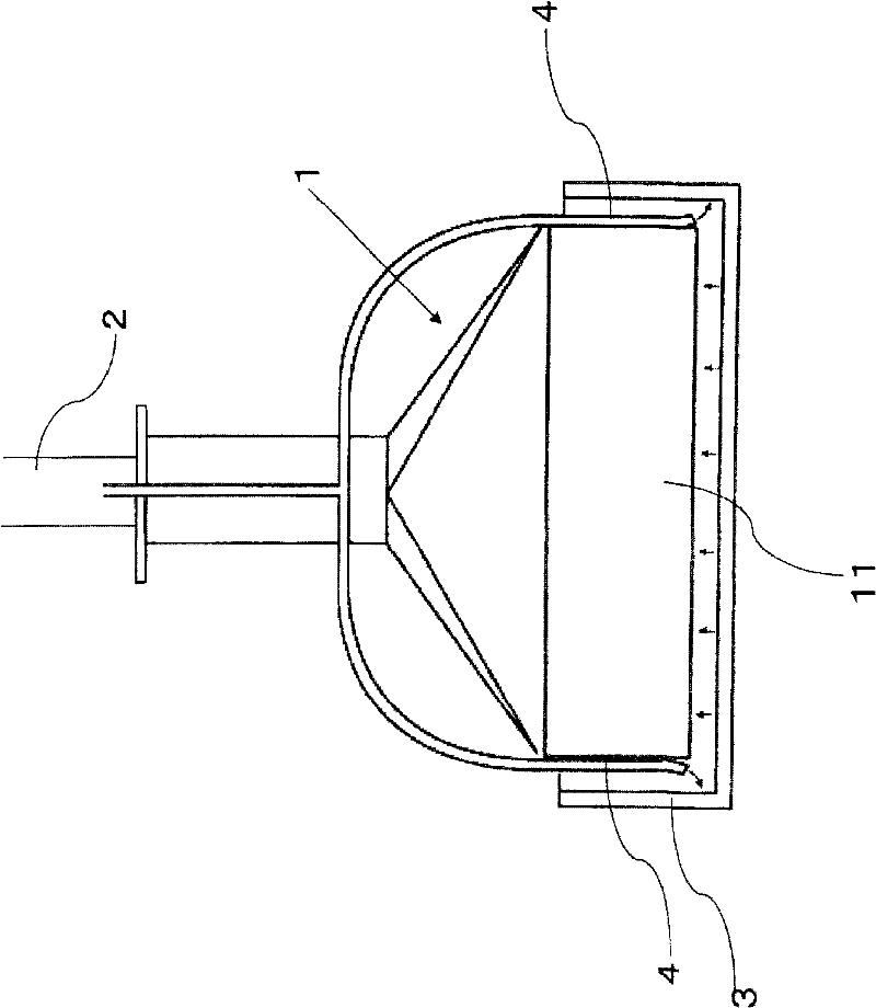
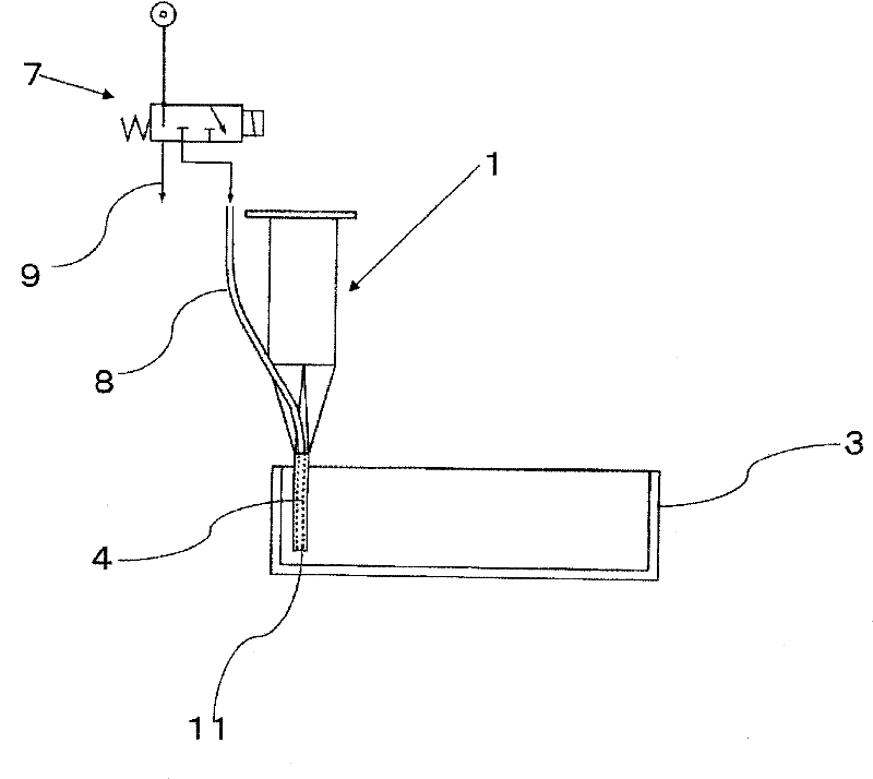
[0031] Next, preferred embodiments of the present invention are shown. figure 1 is the front view of the powder cooling device, figure 2 Yes figure 1 The side view of the cooling device is shown, and, in each drawing, 1 denotes a powder suction nozzle, 2 denotes a transport line, 3 denotes a sagger, and 4 denotes a gas nozzle.

[0032] The powder suction nozzle 1 has a scraper-shaped suction port 11 whose long side is approximately equal to the length of one side of the sagger, and has a gas nozzle 4 on the outer surface of the short side of the suction port.

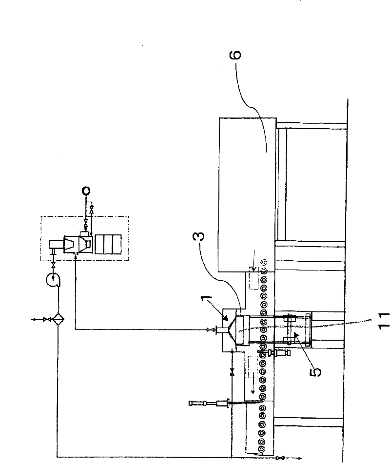
[0033] image 3 It is a figure for demonstrating the cooling device of the powder arrange|positioned at the exit of the continuous firing furnace 6. In this embodiment, if image 3 As shown, there is a sagger moving unit 5 for moving the sagger under the fixedly arranged powder suction nozzle 1 .

[0034] In this embodiment, the powder suction nozzle 1 is fixedly arranged, and if the sagger 3 taken out from the ex...


PUM


Abstract

The invention provides a cooling device for powder burned by a saggar, where the cooling device without long and giant power cooling space has strong cooling effects, and cooling methods related. The powder cooling device comprises a powder nozzle (1) for sucking and recovering powder in the saggar, a powder conveying path (2) for conveying powder recovered by the powder nozzle (1), and a saggar moving unit (5) or a powder nozzle moving unit. The saggar moving unit (5) moves the saggar (3) under the powder nozzle (1) fixedly arranged, and the powder nozzle moving unit moves the powder nozzle (1) above the saggar (3) fixedly arranged. The saggar moving unit (5) or the powder nozzle moving unit has a moving mechanism which moves in segment on the vertical direction and moves continuously on the horizontal direction at a same height, so that powder in the saggar can be sucked in layers.

Description

technical field [0001] The present invention relates to a cooling device for powder fired using a sagger. Background technique [0002] When firing raw material powder for electronic industrial products, the powder is usually placed in a kiln furniture called a sagger and fired (for example, Patent Document 1). Continuous firing is carried out in industrial production. Saggers are put into the furnace sequentially from one end of the continuous furnace with a predetermined firing temperature curve, fired while moving in the furnace, and then taken out from the other end. [0003] The powder in the sagger taken out from the other end of the kiln is recovered in the powder recovery step which is the next step. The powder recovery temperature varies depending on the powder. For example, for powders that need to be fired in a low-oxygen environment, some limit the air exposure temperature after firing to below 50°C. Positive-electrode material (positive-electrode material) Iro...

Claims


Application Information

Patent Timeline
Patent Type & Authority Applications(China)
IPC IPC(8): C01B25/37
CPCC04B35/626C04B35/64C04B2235/70
Inventor 野入一二夫青木道郎
Owner NGK INSULATORS LTD
Why Eureka
Try Eureka