
Method for casting large stamping cylinder casting

A technology for stamping cylinders and castings, applied in casting molding equipment, casting molds, cores, etc., can solve problems such as scrapped castings, slag inclusions in castings, pores, and lowering the qualified rate of castings

Inactive Publication Date: 2011-11-23
RIYUE HEAVY IND
View PDF5 Cites 23 Cited by
  • Summary
  • Abstract
  • Description
  • Claims
  • Application Information

AI Technical Summary

Problems solved by technology

For such large cylindrical parts, some slag substances and air bubbles in the molten iron in the gating system of the traditional casting method are generally deposited at the bottom of the mold, which is easy to cause casting defects, that is, there will be clamping in the casting. slag, pores and other defects; at the same time, it also greatly increases the probability of shrinkage cavity and shrinkage porosity
Therefore, when casting, whether the wall thickness is uniform is the main inspection factor for this long cylindrical casting, and this mainly depends on the size of the residual stress, whether the structural rigidity of the casting is reasonable, whether the rigidity of the sand box is reasonable, the length of the casting, and the strength of the molding sand. And pouring temperature, etc., as long as one or more of these factors fail to meet the requirements, it is very likely that the wall thickness of the casting will be uneven, and eventually the casting will be scrapped, that is, the qualified rate of the finished casting will be reduced.

Method used


Image

  • Method for casting large stamping cylinder casting
  • Method for casting large stamping cylinder casting
  • Method for casting large stamping cylinder casting

Examples


Embodiment Construction

[0034] The present invention will be described in further detail below in conjunction with the accompanying drawings and specific embodiments.

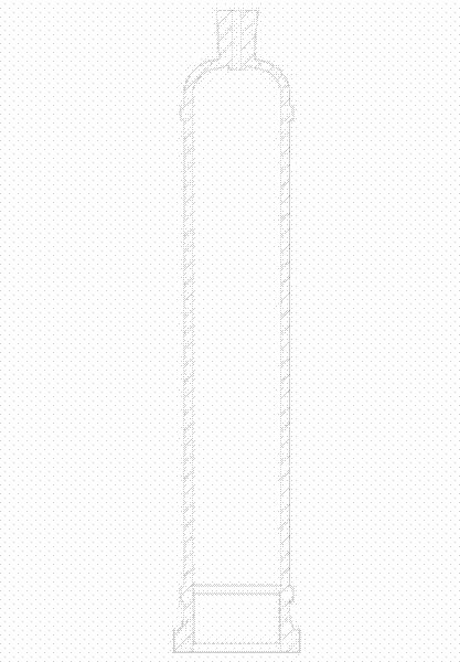
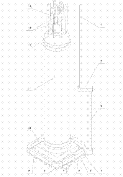
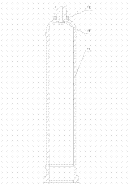
[0035] Depend on Figure 1 ~ Figure 3 As can be seen from each schematic diagram in the casting method of the large stamping cylinder casting of the present invention shown, it comprises the following steps:

[0036] 1) Mold manufacturing;

[0037] 2) Sand mold manufacturing;

[0038] 3) Pouring molding.

[0039] When making sand molds, it includes the following points:

[0040] (2.1) The mold adopts a three-box shape, namely the upper box, the middle box and the lower box. The parting surface of the upper box and the middle box is the end face of the small neck on the upper part of the stamping cylinder, and the parting surface of the middle box and the lower box is the stamping cylinder. The bottom surface of the bottom square flange, the middle box is composed of three boxes;

[0041] (2.2) At the center of the casting cavity ...


PUM


Abstract

The invention discloses a method for casting a large stamping cylinder casting, comprising the following steps of: 1) making a mould; 2) making a sand mould; and 3) pouring and moulding; when the sand mould is made, an upper core cover (19) is embedded in the center of a casting cavity (11) of an upper box, a lower core cover (17) with the same shape and size with the upper core cover (19) is embedded in a sand core (16) inside the casting cavity (11), and a mandril (18) made of iron is sheathed between the upper core cover (19) and the lower core cover (17). By adopting the structure, a gating system, arrangement of a dead head, laying of an cold iron, control of pouring temperature, control of chemical ingredients, control of spheroidization and inoculation and the like are all designed according to the characteristics of the casting, thus the casting defect that slag inclusion, an air hole and the like are produced can be overcome; and the probability that a shrinkage cavity and shrinkage porosity are caused can be reduced, thus the yield of casting finished products can be greatly improved.

Description

technical field [0001] The invention relates to a casting method of a large stamping cylinder casting. Background technique [0002] As the technology of the plastic machinery industry becomes more and more mature, the size requirements of plastic products are getting larger and larger, and the machinery and equipment used to produce plastic products are becoming larger and larger, and the size of parts of plastic machinery is also increasing accordingly. Among them, stamping The cylinder is one of the key components in the injection molding machine, which is generally made by casting. For large injection molding machines, the casting weight of the stamping cylinder can reach 10500Kg, the pouring weight of the casting can reach 13000T, the main wall thickness can reach 105mm, the maximum wall thickness can reach 190mm, the height of the external dimension can reach 4115mm, and the diameter can reach 1050mm. For such large cylindrical parts, some slag substances and air bub...

Claims


Application Information

Patent Timeline
Patent Type & Authority Applications(China)
IPC IPC(8): B22C9/24C22C37/04C22C33/10
Inventor 马超宋贤发傅明康
Owner RIYUE HEAVY IND
Learn More