A casting multi-layer pouring system and process

A pouring system and gate technology, applied in the direction of manufacturing tools, casting molding equipment, casting molds, etc., can solve the problems of inaccurate dimensional accuracy of castings, waste of resources, uneven shrinkage, etc., to save materials and energy, reduce production costs, Good flow direction and flow speed effect

Inactive Publication Date: 2018-01-05
HUBEI YAGANG METAL MFR
View PDF9 Cites 5 Cited by
  • Summary
  • Abstract
  • Description
  • Claims
  • Application Information

AI Technical Summary

Problems solved by technology

[0003] In traditional sand casting, generally each sand mold can only be poured once, and the sand mold casts a casting product, and the mold will be damaged after the casting is obtained; single casting casting, in the mass production of castings, occupies a large area, sand casting The production efficiency is low, and a casting requires an upper mold, a lower mold, and even a middle mold, which shows that the casting process is inefficient and wastes resources
[0004] For this reason, it is necessary to improve the sand casting process. People study the process of overlapping casting molds to obtain higher casting production efficiency. In the stacking casting process of castings, molten iron is pouring from top to bottom Pouring the lower layer of molten iron first, and pouring the upper layer in turn, will cause the composition and temperature of the molten iron to be uneven, and the shrinkage will be uneven, especially when pouring large castings, the fluidity of the molten iron is large More obviously, there are also quality defects such as pores, shrinkage cavities, slag inclusions, and cold shuts due to pressure differences, which seriously affect the quality of castings, make the dimensional accuracy of castings seriously inaccurate, and affect the yield of castings; at the same time, it is still inevitable to use the bottom mold , cover mold, etc., waste of resources, cumbersome process

Method used


Image

  • A casting multi-layer pouring system and process
  • A casting multi-layer pouring system and process
  • A casting multi-layer pouring system and process

Examples


Embodiment Construction

[0023] The present invention will be further described below in conjunction with drawings and embodiments.

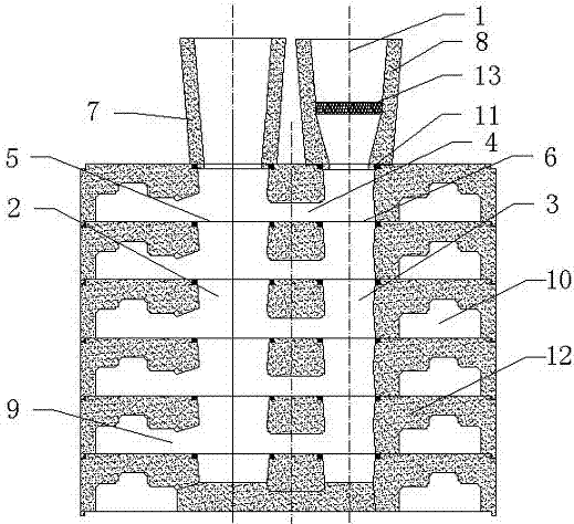
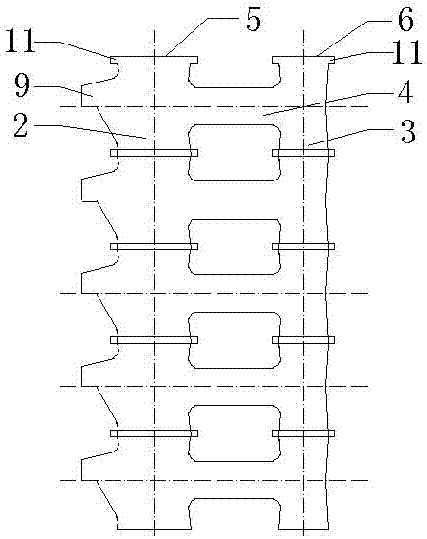
[0024] Such as figure 1 , 2 As shown in , 3, a casting multi-layer pouring system, the pouring system is made of metal material casting and processing to form a mold, the product mold and the pouring system mold are mechanically operated to form a product pouring system cavity and a sand mold cavity, and the pouring system is multiple Layers and stacked, according to the requirements of the number of stacked layers required for the production of products, determine the matching process of the gating system and the product, and stack and fasten the multi-layer gating system sets.

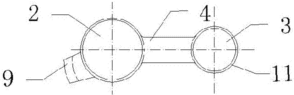
[0025] The gating system 1 is a pouring cavity, and the gating system 1 is respectively provided with a riser 2 and a sprue 3. Each layer of the gating system 1 is provided with a cross sprue 4 between the riser 2 and the sprue 3. Riser channels 2 and sprue channels 3 are formed in the entir...


PUM


Abstract

The invention discloses a casting multi-layered pouring system and process, which is characterized in that: the pouring system is multi-layered and stacked respectively, the pouring system is respectively provided with a riser channel and a sprue, each layer of the pouring system, a riser The upper and lower ends of the sprue and the sprue are respectively provided with a riser and a gate. The top riser and the gate of the gating system are respectively fastened with a riser cup and a sprue cup. The riser and the gate at the lower end of each layer of the gating system are respectively tight. Set on the riser and gate at the upper end of the gating system of the next layer, the riser and gate at the bottom of the gating system are sealed separately, a horizontal runner is provided between the riser channel and the sprue, and a The ingate, the runner leads to the ingate, and the ingate communicates with the cavity of the product sand model. The present invention casts multi-layer product sand mold cavities by setting a multi-layer pouring system, improves the production efficiency of castings, shortens the pouring time, ensures the composition and temperature balance of multi-layer pouring molten iron, and guarantees the quality of pouring products.

Description

technical field [0001] The invention relates to the technical field of casting, in particular to a casting multi-layer pouring system and technology. Background technique [0002] The casting process can be divided into gravity casting, pressure casting and sand casting. Sand molds generally adopt gravity casting, and low-pressure casting, centrifugal casting and other processes can also be used when there are special requirements. Sand casting has a wide range of adaptability. There are wooden molds for sand casting. In addition to single-piece sand castings, aluminum alloy molds or resin molds with high dimensional accuracy and long service life can be used. Although the price has increased, it is still much cheaper than molds for metal casting, especially in small batch and large-scale production. In addition, sand molds have higher refractoriness than metal molds, so materials with higher melting points such as copper alloys and ferrous metals also use this process. ...

Claims


Application Information

Patent Timeline
Patent Type & Authority Patents(China)
IPC IPC(8): B22C9/20B22C9/08
Inventor 杨友忠程增安
Owner HUBEI YAGANG METAL MFR
Why Eureka
Try Eureka