Liquid steel casting equipment

A liquid steel and liquid state technology, applied in the field of liquid steel pouring equipment, can solve the problems of microscopic defects, high manufacturing cost, long production cycle, etc., achieve the effects of improving the temperature field distribution, easy operation of the method, and reducing the phenomenon of slag entrainment

Active Publication Date: 2011-11-23
郭秀梅
View PDF13 Cites 3 Cited by
  • Summary
  • Abstract
  • Description
  • Claims
  • Application Information

AI Technical Summary

Problems solved by technology

[0003] With the development of the national economy, steel for nuclear power, steel for boilers and pressure vessels, steel for wind power flanges, steel for bridges, high-rise buildings and other structural steels have increasingly strict requirements on the internal quality of steel plates. To ensure the internal quality of steel plates, most of them use forging, Electroslag remelting and directional solidification are used to produce this type of steel plate, but due to its long production cycle and high manufacturing costs, it restricts enterprises to further reduce production costs
For steel ingots cast by conventional ingot molds, the sprue is at the center of the ingot mould. According to the knowledge of metallurgical transmission principles, the relative temperature of the steel flow in the vertical direction of the sprue is high, which will easily cause serious segregation and central porosity inside the ingot. Severe segregation and porosity in the center of the steel ingot are difficult to eliminate and alleviate in subsequent processes. Therefore, the rolled steel plate, especially the extra-thick steel plate ≥ 200mm, often has microscopic defects inside, which may easily cause flaw detection failures.

Method used


Image

  • Liquid steel casting equipment
  • Liquid steel casting equipment
  • Liquid steel casting equipment

Examples


Embodiment 1

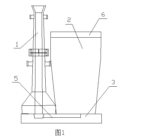
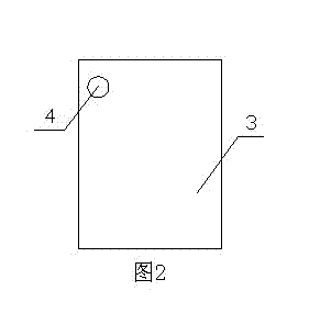
[0018] Such as figure 1 , figure 2 Shown: a liquid steel pouring equipment, including an ingot mold 2, the upper part of the ingot mold 2 is provided with a thermal insulation cap 6, the ingot mold 2 is arranged on the ingot mold chassis 3, and a flow steel channel is arranged in the ingot mold chassis 3 5. The flow steel channel 5 communicates with the center injection pipe 1 arranged on one side of the ingot mold 2, the flow steel channel 5 communicates with the pouring port 4 on the bottom of the ingot mold, and the bottom of the ingot mold 2 deviates from the ingot mold 2 A sprue 4 is arranged at the center of the bottom, near the bottom corner of the ingot mould. There are three ingot moulds, each of which can pour 33t of molten steel. The 280mm thick low-alloy Q345B steel plate that meets the F2 standard of forging flaw detection can be produced by using this equipment and a suitable process. At present, 18 ingots are produced, the thickness of the steel plate is 200...

Embodiment 2

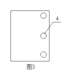
[0020] Such as figure 1 , image 3 Shown: a liquid steel pouring equipment, including an ingot mold 2, the upper part of the ingot mold 2 is provided with a thermal insulation cap 6, the ingot mold 2 is arranged on the ingot mold chassis 3, and a flow steel channel is arranged in the ingot mold chassis 3 5. The flow steel channel 5 communicates with the center injection pipe 1 arranged on one side of the ingot mold 2, and the flow steel channel 5 communicates with the three pouring ports 4 on the side of the ingot mold, and the pouring ports 4 deviate from the ingot mold 2 Bottom center position. The diameter of the center injection pipe is 80mm, and the diameter of the sprue is 60mm; there are two ingot moulds, each of which can pour 43t of molten steel. The 250mm thick low-alloy Q345D steel plate that meets the F2 standard of forging flaw detection can be produced by using this equipment and a suitable process. At present, 12 ingots are produced, the thickness of the stee...

Embodiment 3

[0022] Such as figure 1 , Figure 4 Shown: a liquid steel pouring equipment, including an ingot mold 2, the upper part of the ingot mold 2 is provided with a thermal insulation cap 6, the ingot mold 2 is arranged on the ingot mold chassis 3, and a flow steel channel is arranged in the ingot mold chassis 3 5. The flow steel channel 5 communicates with the center injection pipe 1 arranged on one side of the ingot mold 2, the flow steel channel 5 communicates with the pouring port 4 on the bottom of the ingot mold, and the bottom of the ingot mold 2 deviates from the ingot mold 2 A sprue 4 is arranged at the center position of the bottom, at 1 / 4 of the length (width) direction of the center line of the bottom of the ingot mould. The diameter of the middle injection pipe is 80mm, and the diameter of the sprue is 60mm; there are two ingot moulds, each of which can pour 48t of molten steel.

[0023] The 240mm thick low-alloy Q345B steel plate that meets the F2 standard of forging ...


PUM

PropertyMeasurementUnit
thicknessaaaaaaaaaa
diameteraaaaaaaaaa
diameteraaaaaaaaaa

Abstract

The invention discloses liquid steel casting equipment. The liquid steel casting equipment comprises an ingot mold, wherein the upper part of the ingot mold is provided with a hot top; the ingot mold is arranged on an ingot mold base plate; a steel flow channel is formed in the ingot mold base plate, is communicated with a central casting pipe arranged on one side of an ingot mold body and is communicated with casting gates at the bottom of the ingot mold; and at least one casting gate is formed at the position which is deviated from the bottom center of the ingot mold. The liquid steel casting equipment can prevent the phenomenon of slag entrainment in the process of casting liquid steel by changing the position and the quantity of the ingot mold casting gates, deviating the casting gates from the bottom center or increasing a plurality of casting gates, changes the flow field distribution and the temperature field distribution of the liquid steel inside the ingot mold in the process of casting the liquid steel or after the casting, overcomes the defects of center segregation and loosing of steel ingots and can change the segregation positions of the steel ingots to make a segregation off center close to a steel ingot rolling surface at the same time.

Description

[0001] technical field [0002] The invention belongs to the technical field of production equipment for smelting, and in particular relates to a liquid steel pouring equipment. Background technique [0003] With the development of the national economy, steel for nuclear power, steel for boilers and pressure vessels, steel for wind power flanges, steel for bridges, high-rise buildings and other structural steels have increasingly strict requirements on the internal quality of steel plates. To ensure the internal quality of steel plates, most of them use forging, Electroslag remelting and directional solidification are used to produce this type of steel plate, but due to its long production cycle and high manufacturing costs, enterprises are restricted from further reducing production costs. For steel ingots cast by conventional ingot molds, the sprue is at the center of the ingot mould. According to the knowledge of metallurgical transmission principles, the relative tempera...

Claims


Application Information

Patent Timeline
Patent Type & Authority Applications(China)
IPC IPC(8): B22D7/06
CPCB22D7/06B22D7/10
Inventor 朱书成
Owner 郭秀梅
Why Eureka
Try Eureka