Protrusion type partition reactor

A reactor, raised technology, applied in the field of raised partitioned reactors, can solve problems affecting the service life of refractory bricks, refractory material ablation, single-nozzle gasifier capacity limitation, etc.

Active Publication Date: 2015-09-23
XIAN ORIGIN CHEM TECH
View PDF7 Cites 0 Cited by
  • Summary
  • Abstract
  • Description
  • Claims
  • Application Information

AI Technical Summary

Problems solved by technology

[0003] The advantage of the single-nozzle direct-injection gasifier lies in its simple structure and control, and low cost. However, since the pressurized gasification process involves high temperature, high pressure, fluid flow under heterogeneous In the chemical reaction process, the production capacity of the single-nozzle gasifier is greatly limited,

Method used


Image

  • Protrusion type partition reactor

Examples


Embodiment 1

[0057] Embodiment 1: Convex zone reactor of the present invention

[0058] The implementation mode of this embodiment is as follows:

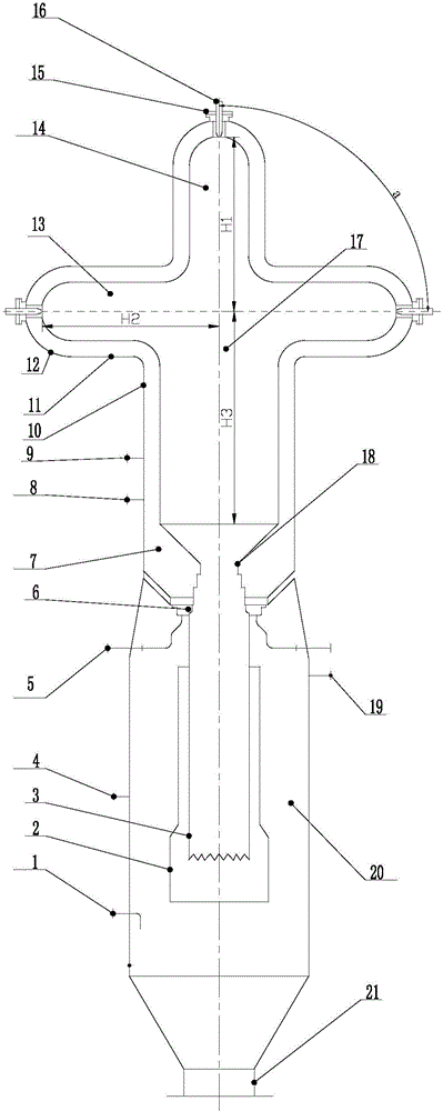
[0059] The raised zone reactor of the present invention includes a reaction chamber 17 and a cooling chamber 20 . The reaction chamber 17 communicates with the cooling chamber 20 through the slag port 18, and the reaction chamber 17 and the cooling chamber 20 have a common central axis; the inner wall of the reaction chamber 17 is paved with a refractory lining 7 made of high-temperature refractory bricks.

[0060] The reaction chamber 17 is made up of a vertical reaction zone 14 and 2-12 lateral reaction zones 13, and the vertical reaction zone 14 and the side reaction zone 13 are all bell-shaped structures, and are all arranged on their tops for installing nozzles 16 nozzle mounting openings 15, the central axis of the installation nozzle 16 coincides with the corresponding reaction zone central axis; the side reaction zone 13 (i.e. the vert...

Embodiment 2

[0065] Embodiment 2: Raised type partition reactor of the present invention

[0066] The implementation of this embodiment is the same as that of Example 1, except that a lateral reaction zone 13 is arranged at the lower end of the vertical reaction zone 14, and the included angle α between the longitudinal axis of the vertical reaction zone 14 and the longitudinal axis of the lateral reaction zone 13 is 30°. The ratio of the length H1 of the vertical reaction zone 14 to the length H2 of the lateral reaction zone 13 is 1.0. The ratio of the height H1 of the vertical reaction zone 14 at the upper part of the reaction chamber 17 to the height H3 of the cylinder 10 at the lower part of the reaction chamber 17 is 0.2.

Embodiment 3

[0067] Embodiment 3: Raised type partition reactor of the present invention

[0068] The implementation of this embodiment is the same as that of Example 1, except that a lateral reaction zone 13 is arranged at the lower end of the vertical reaction zone 14, and the included angle α between the longitudinal axis of the vertical reaction zone 14 and the longitudinal axis of the lateral reaction zone 13 is 150°. The ratio of the length H1 of the vertical reaction zone 14 to the length H2 of the lateral reaction zone 13 is 2.4. The ratio of the height H1 of the vertical reaction zone 14 at the upper part of the reaction chamber 17 to the height H3 of the cylinder 10 at the lower part of the reaction chamber 17 is 3.0.


PUM


Abstract

The invention relates to a protrusion type partition reactor. The protrusion type partition reactor comprises a reaction chamber 17 and a cooling chamber 20, the reaction chamber 17 is communicated with the cooling chamber 20 through a slag port 18, and the reaction chamber 17 and the cooling chamber 20 have the joint central axis. Compared with an existing gasifier, the protrusion type partition reactor has the advantages of being large in coal feeding amount, high in gasification efficiency, long in service life of a refractory lining and the like. Synthesis gas produced by utilizing the protrusion type partition reactor can be used as chemical engineering raw material gas and fuel gas, can be used for preparing hydrogen and synchronizing liquid fuels and the like, and is extremely wide in application.

Description

【Technical field】 [0001] The invention belongs to the technical field of clean and efficient utilization of energy. More specifically, the present invention relates to a raised zoned reactor. 【Background technique】 [0002] Gasification technology using hydrocarbons as raw materials has been widely used in synthetic ammonia, synthetic methanol industry, power generation (IGCC), coal-to-oil and other technical fields. This reactor is used to produce syngas CO+H 2 Therefore, many scientific and technical personnel have developed various types of reactors. In the existing advanced entrained entrained gasification technology, the reactors used include coal water slurry gasifier, GSP, Shell pulverized coal gasifier, etc. At the same time, the reactor can be divided into a single-nozzle gasifier and a multi-nozzle gasifier according to the feeding method, furnace lining, number and arrangement of nozzles, and different gasifiers have their own advantages and disadvantages. [0...

Claims


Application Information

Patent Timeline
IPC IPC(8): C10J3/48C10J3/84C10J3/72C01B3/50C01B3/36
CPCY02E20/18
Inventor 朱春鹏门长贵徐宏伟贺根良韦孙昌徐红东罗进成张晓慧杜彦学李璞袁善录
Owner XIAN ORIGIN CHEM TECH
Why Eureka
Try Eureka