
Thermit reaction foil, manufacturing method thereof and application thereof to welding process

A technology of aluminothermic reaction and manufacturing method, applied in aluminothermic welding equipment, welding medium, manufacturing tools, etc., can solve problems affecting welding strength, weld structure and density are not very high, no power supply, etc., and achieve fast response speed , High welding strength and fast welding speed

Inactive Publication Date: 2011-11-23
NINGBO INST OF MATERIALS TECH & ENG CHINESE ACADEMY OF SCI
View PDF5 Cites 22 Cited by
  • Summary
  • Abstract
  • Description
  • Claims
  • Application Information

AI Technical Summary

Problems solved by technology

However, in the welding and repair of ceramic armor and its armor parts, traditional welding mainly has the following problems: First, the thermal expansion coefficient between the armor and parts to be welded and the base material is very different, resulting in welding cooling and sudden temperature changes. The stress generated by the welding seam seriously affects the welding strength; second, welding equipment and electrical energy are needed, and the armored equipment under field conditions not only does not carry on-board electric welding equipment, but also does not have power supply and gas storage equipment. Therefore, the traditional welding method Can not meet the needs of armor emergency repair; The 3rd, weld metal mostly is free crystallization, and weld structure and density are not very high, so urgently need a kind of welding of ceramic armor under the condition that does not need electricity, does not need gas and equipment is simple, also Solve the emergency welding repair of armor equipment and parts under field conditions

Method used


Image

  • Thermit reaction foil, manufacturing method thereof and application thereof to welding process
  • Thermit reaction foil, manufacturing method thereof and application thereof to welding process
  • Thermit reaction foil, manufacturing method thereof and application thereof to welding process

Examples


Embodiment Construction

[0037] The present invention will be further described in detail below in conjunction with the accompanying drawings and specific embodiments.

[0038] The symbols in the drawings are: thermite reaction foil 1, aluminum layer 2, zinc oxide layer 3, silicon substrate 4, photoresist 5, thermite 6, welding groove 7, substrate 8, substrate 9, substrate 10, Substrate 11, solder 12.

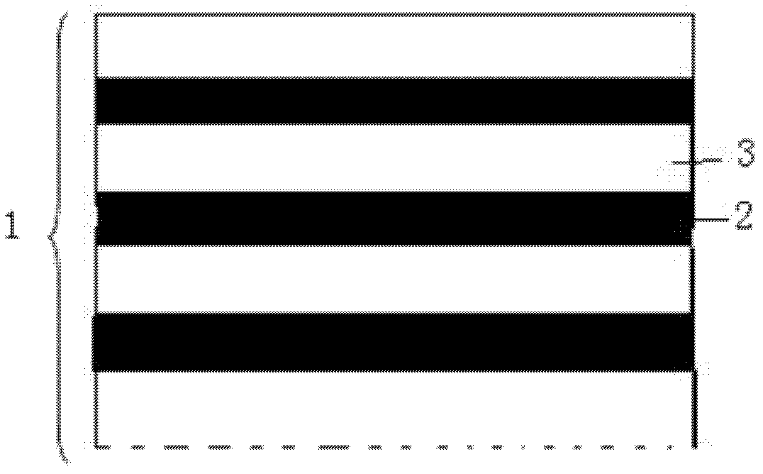
[0039] Such as figure 1 As shown, the thermite reaction foil 1 is composed of an aluminum layer 2 and a zinc oxide layer 3, and the aluminum layer 2 and the zinc oxide layer 3 are alternately stacked up and down. The sum of the thicknesses of the single-layer aluminum layer 2 and the zinc oxide layer 3 is 10-50 nm, and the total thickness of the aluminothermic reaction foil 1 is 5-50 μm.

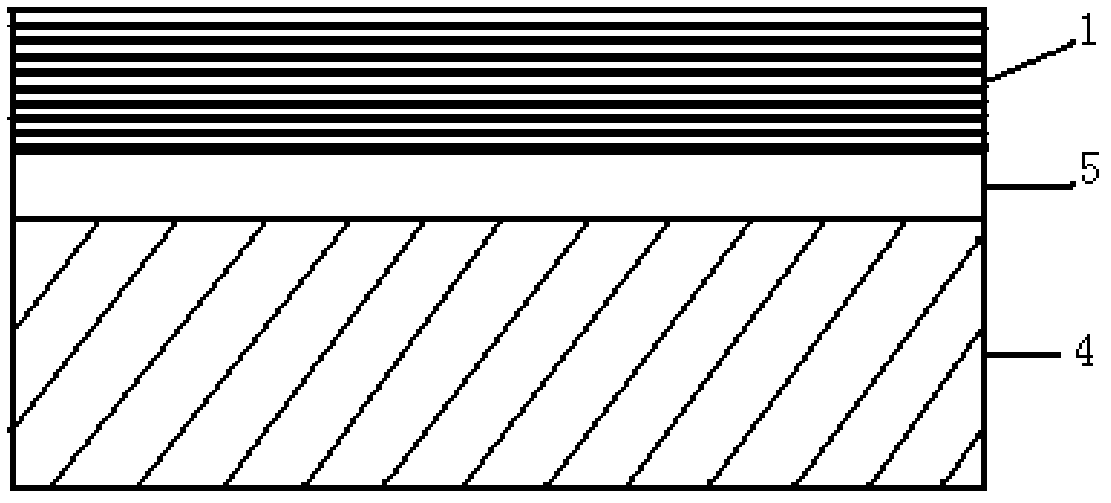
[0040] The above-mentioned thermite reactive foil 1 is deposited by magnetron sputtering technology. Such as image 3 As shown, first a layer of photoresist 5 is coated on the surface of the silicon substrate 4, ...


PUM

PropertyMeasurementUnit
Thicknessaaaaaaaaaa
Thicknessaaaaaaaaaa
Widthaaaaaaaaaa

Abstract

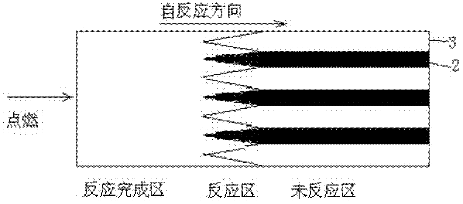
The invention belongs to the technical field of thermit welding and discloses a thermit reaction foil. The thermit reaction foil consists of aluminum and a metal oxide capable of generating the thermit reaction with the aluminum, wherein each of the aluminum and the metal oxide has a laminated structure with at least one layer; and the aluminum layer and the metal oxide layer are arranged sequentially in an overlapping mode. When excitation with certain heat is applied to one end face of the thermit reaction foil, the thermit reaction foil generates self-propagating reaction instantly and other thermite or melting solder is ignited by heat released by the reaction, so that materials are welded. Therefore, compared with the prior art, the thermit reaction foil has reaction time of only several milliseconds, high reaction heat release, high welding speed and high welding strength, can weld the materials with different coefficient of thermal expansion, and is easy to operate, applicable to welding of various armors and parts and emergent welding repair of battlefields and also applicable to welding of various fine parts.

Description

technical field [0001] The invention belongs to the technical field of thermite welding, and in particular relates to a thermite reaction foil and its manufacturing method, and the application of the thermite reaction platinum as an ignition agent and an internal heat source in a welding process, and is suitable for welding various small parts Welding, welding of various armor and parts, as well as field work of armored vehicles, emergency repairs on battlefields and other welding processes. Background technique [0002] The application of melting iron and alumina using the heat released from the reaction of iron oxide and aluminum powder has been used in welding for nearly 100 years. This thermite reaction is most commonly used in high-temperature outdoor operations such as orbital welding. In use, molten metal flows from the furnace into the mold to be welded, and low-density alumina floats on the upper layer of the furnace and is finally removed. However, the reaction be...

Claims


Application Information

Patent Timeline
IPC IPC(8): B23K23/00B23K35/22
Inventor 黄峰李艳玲葛芳芳朱萍薛群基
Owner NINGBO INST OF MATERIALS TECH & ENG CHINESE ACADEMY OF SCI
Learn More