
Permanent magnetic workbench

A technology of permanent magnet worktable and magnetic pole, applied in manufacturing tools, metal processing equipment, metal processing machinery parts, etc. The scope of application and other issues, to achieve the effect of improving the utilization rate and applicability, and expanding the scope of adsorption

Active Publication Date: 2011-11-23
南昌永旺机电设备有限公司
View PDF6 Cites 7 Cited by
  • Summary
  • Abstract
  • Description
  • Claims
  • Application Information

AI Technical Summary

Problems solved by technology

[0005] However, since the magnetic pole group is fixed on the solid base plate through a fixed structure, the internal magnetic pole is affected by the internal coercive force when the internal magnetic pole is twisted, and the length of the internal magnetic pole is greatly limited (usually below 800mm at present). move, or easily twist off the inner magnetic pole connector
Therefore, when the diameter of the circular permanent magnet table is too large, its inner hole (that is, the part without the magnetic pole working surface) must also be enlarged, thus limiting the magnetic pole working surface of the permanent magnet worktable.
For example, for a circular permanent magnet table with a diameter of 2800mm, the diameter of the inner hole must be 1600mm larger. Since the workpiece cannot be adsorbed within the inner hole, this seriously limits the utilization rate and scope of application of the large permanent magnet workbench, which is especially unsuitable. Suitable for machining ring workpieces with different diameters

Method used


Image

  • Permanent magnetic workbench
  • Permanent magnetic workbench
  • Permanent magnetic workbench

Examples


Embodiment Construction

[0028] Embodiments of the present invention are described in detail below, examples of which are shown in the drawings, wherein the same or similar reference numerals designate the same or similar elements or elements having the same or similar functions throughout. The embodiments described below by referring to the figures are exemplary only for explaining the present invention and should not be construed as limiting the present invention.

[0029] In describing the present invention, it should be understood that the terms "center", "longitudinal", "transverse", "upper", "lower", "front", "rear", "left", "right", " The orientations or positional relationships indicated by "vertical", "horizontal", "top", "bottom", "inner", "outer", etc. are based on the orientation or positional relationships shown in the drawings, and are only for the convenience of describing the present invention and simplifying Describes, but does not indicate or imply that the device or element referred...


PUM


Abstract

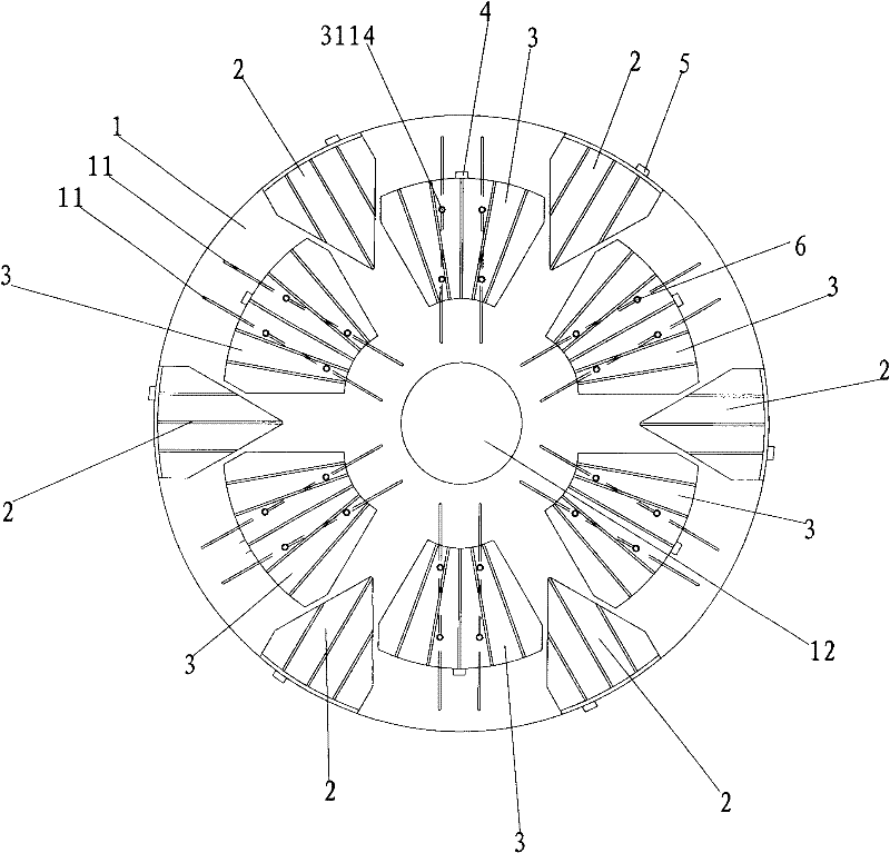
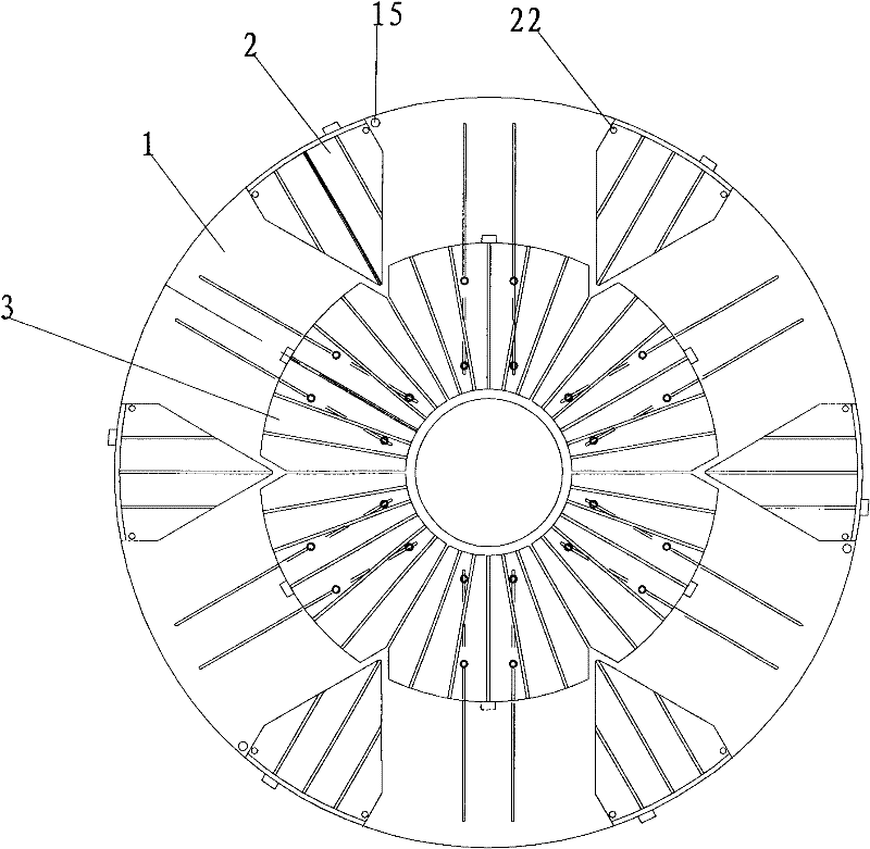
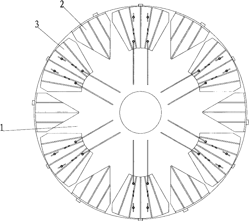
The invention discloses a permanent magnetic workbench which comprises a chassis and a plurality of first magnetic pole groups arranged at intervals on the circumference of the chassis, wherein each magnetic pole group is arranged in the radial direction of the chassis and adjustably positioned on the upper surface of the chassis; each magnetic pole group comprises a plurality of unit magnetic poles; two adjacent unit magnetic poles are magnetically isolated from each other; each unit magnetic pole comprises an outer magnetic pole, an inner magnetic pole arranged inside each outer magnetic pole and at least one magnetic source arranged inside each outer magnetic pole or each inner magnetic pole; and the inner magnetic poles can rotate inside the outer magnetic poles to ensure the magnetization and demagnetization of the unit magnetic poles. According to the permanent magnetic workbench disclosed by the invention, the size of the magnetic pole working surface is changeable so that the utilization rate and the applicability are improved.

Description

technical field [0001] The invention relates to a workbench, in particular to a permanent magnet workbench. Background technique [0002] At present, in the milling, grinding, planing and other processing of metal workpieces, most of the workpieces are clamped and fixed by the T-shaped slots of the cast iron workbench with bolts and weights, and the weights and bolts are removed after processing. This workpiece fixing method has the problems of low precision and low processing efficiency. [0003] In order to overcome the above problems, electromagnetic and small permanent magnet workbenches have been proposed in the prior art, but the magnetic force of the traditional small permanent magnet workbench is small. The electromagnetic workbench uses coils and iron cores to generate a magnetic field. The coils and wires are easily damaged by the processing coolant, and the insulation layer is broken down, which is easy to cause electric shock accidents. [0004] For this reason...

Claims


Application Information

Patent Timeline
Patent Type & Authority Applications(China)
IPC IPC(8): B23Q3/154B23Q1/03B23Q1/25
Inventor 陈玉争
Owner 南昌永旺机电设备有限公司
Learn More