Portable head position and support system for cataract blind prevention surgeries
A stent system and cataract technology, applied in the field of medical devices, can solve problems such as not equipped with a stent, affecting the patient's breathing, and inconvenient use of surgical drape
- Summary
- Abstract
- Description
- Claims
- Application Information
AI Technical Summary
Problems solved by technology
Method used
Image
Examples
Embodiment 1
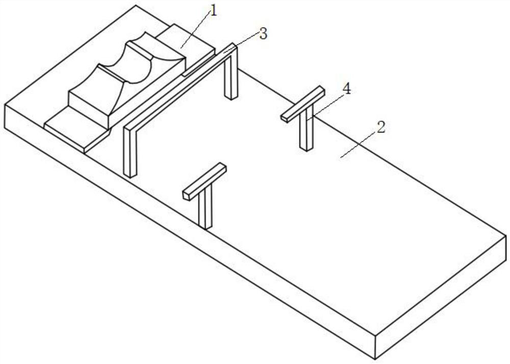
[0097] The embodiment of the present invention provides a portable head position and bracket system for cataract blindness prevention surgery, such as Figure 1-10 shown, including:
[0098] Head position support and adjustment assembly 1, the head position support and adjustment assembly 1 is detachably connected to the operating bed 2; preferably, the above head position support and adjustment assembly 1 can be an existing adjustable head fixation device (especially It is the corresponding head fixation device in the operation), and it can also be the body and connecting part disclosed in CN 111789737 A;
[0099] The first connection bracket 3 is detachably connected with the operating bed 2 through the first connection device 5 (which may be an existing bolt assembly);
[0100]The auxiliary connection bracket 4 is detachably connected to the operating bed 2 and is located on the side of the first connection bracket 3 away from the head support and adjustment assembly 1 . ...
Embodiment 2
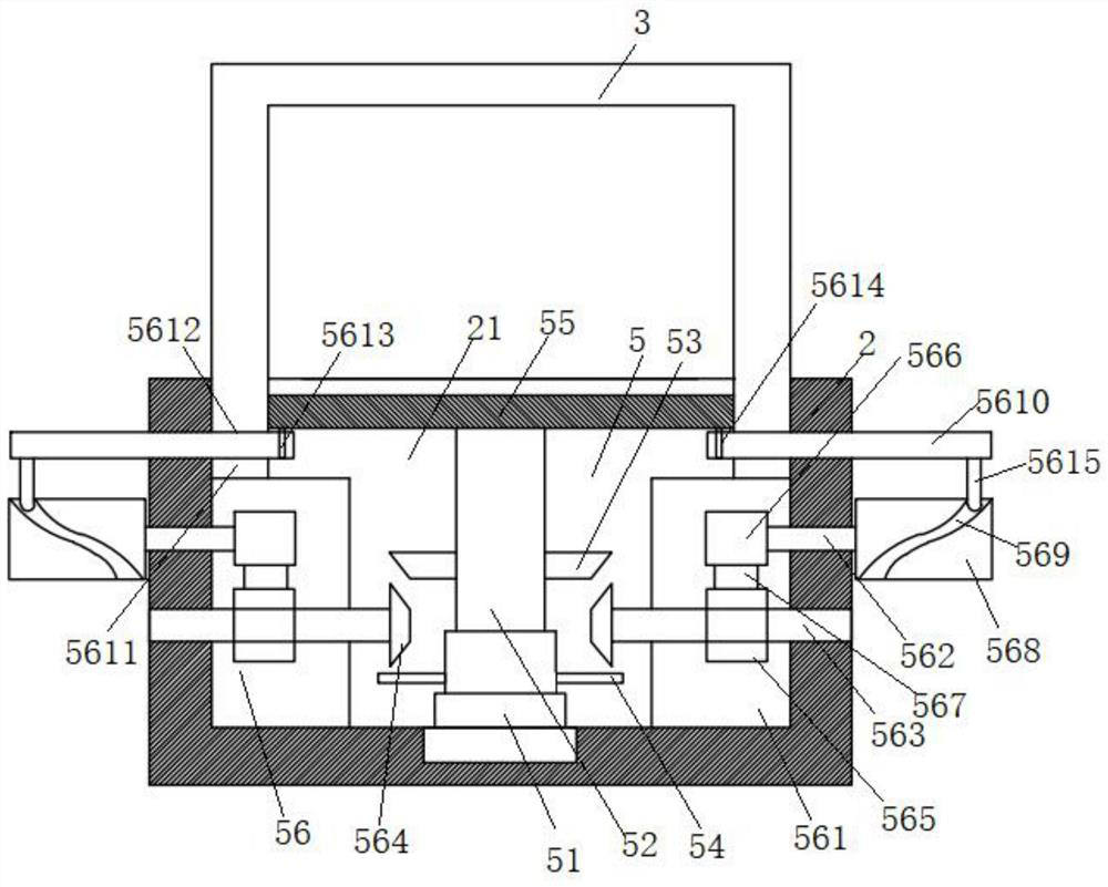
[0104] Such as figure 2 as shown, figure 2 Middle is the internal side view of the operating bed viewed from one side in the width direction (specifically, when the length direction is the front-to-back direction, the figure 2 is the front or rear interior side view);
[0105] The upper end of the operating bed 2 is provided with an installation cavity 21, the length direction of the operating bed 2 is the front-rear direction, the side and top surface of the installation cavity 21 are provided with a number of ventilation holes, and the first connecting device 5 includes:
[0106] The first driving motor 51 is vertically arranged at the bottom end of the installation cavity 21;
[0107] The first telescopic rod 52, the fixed end of the lower end is fixedly connected to the output end of the upper end of the first driving motor 51;
[0108] The first bevel gear 53 is fixedly socketed on the telescopic end of the first telescopic rod 52;
[0109] The fan blade 54 is fixe...
Embodiment 3
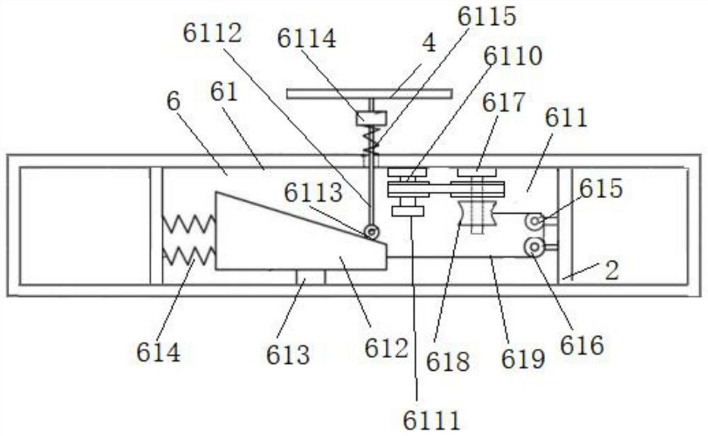
[0130] On the basis of embodiment 1 or 2, image 3 Middle is the internal side view of the operating bed viewed from one side in the length direction (specifically, when the length direction is the front-to-back direction, the figure 2 It is a left or right internal side view) The auxiliary connecting bracket 4 is detachably connected to the operating bed 2 through the second connecting device 6, and the second connecting device 6 includes:
[0131] Two second connecting components 61, the length direction of the operating bed is the front and rear direction, the two second connecting components are symmetrically arranged on the operating bed 2, and are located on the first connecting bracket 3 away from the head support and Adjust one side of component 1;
[0132] The second connection assembly 61 includes:
[0133] The adjustment cavity 611 is set on the upper part of the operating bed 2;
[0134] Moving block 612, the lower end is fixedly connected with the 3rd sliding ...
PUM
 Abstract
Description
Claims
Application Information
 - R&D
- Intellectual Property
- Life Sciences
- Materials
- Tech Scout
- Unparalleled Data Quality
- Higher Quality Content
- 60% Fewer Hallucinations
Browse by: Latest US Patents, China's latest patents, Technical Efficacy Thesaurus, Application Domain, Technology Topic, Popular Technical Reports.
© 2025 PatSnap. All rights reserved.Legal|Privacy policy|Modern Slavery Act Transparency Statement|Sitemap|About US| Contact US: help@patsnap.com


