Comb driver with self-cleaning function

A driver and comb-tooth technology, applied in the field of micro-electromechanical, can solve the problems of comb-tooth driver and device failure, etc., and achieve the effects of low cost, easy processing, and improved reliability

Active Publication Date: 2019-01-22
XI AN ZHISENSOR TECH CO LTD
View PDF5 Cites 2 Cited by
  • Summary
  • Abstract
  • Description
  • Claims
  • Application Information

AI Technical Summary

Problems solved by technology

Although the electrostatic comb driver device generally needs to be packaged and sealed for use, due to the limitations of the packaging environment, packaging materials, and packaging costs, a certain number of particles may still exist or regenerate in the working space of the packaged electrostatic comb driver device. , according to the characteristics of the charged body to absorb light and small objects, during the working process of the comb drive, it will be deposited around the electrodes of the comb drive, which will cause the failure of the comb drive and devices

Method used


Image

  • Comb driver with self-cleaning function
  • Comb driver with self-cleaning function
  • Comb driver with self-cleaning function

Examples


Embodiment 1

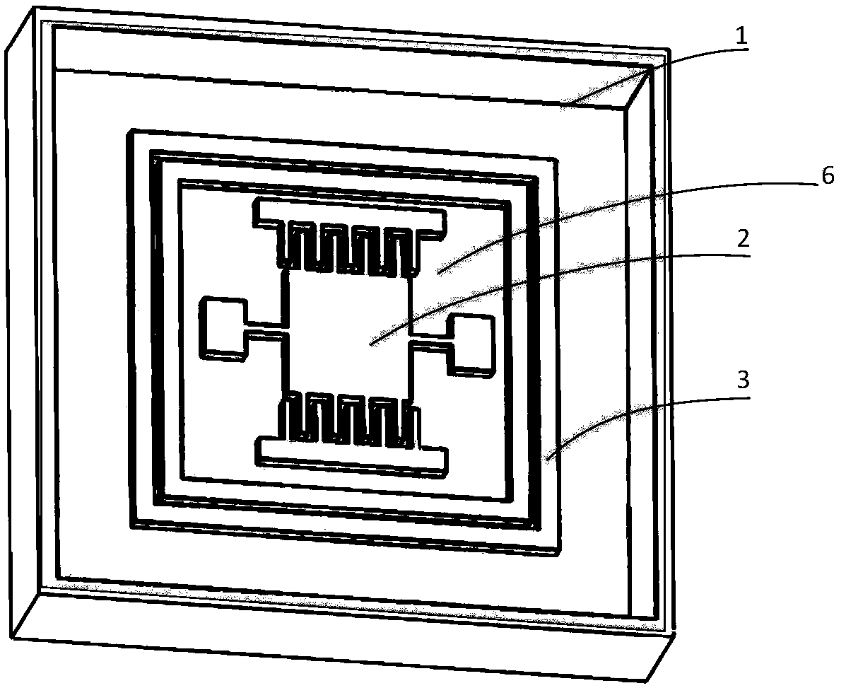
[0030] from figure 1 It can be seen that the self-cleaning comb driver in this embodiment mainly includes a closed casing 1 , a drive comb 2 , a silicon substrate 6 and an adsorption electrode 3 . The driving comb 2 and the adsorption electrode 3 are arranged on the silicon substrate 6 and located inside the closed casing 1. The closed casing 1 provides a closed working space for the comb driver to isolate the interference from the external space; the driving comb 2 drives the MEMS device to work, and the adsorption Electrode 3 is used to adsorb particles in the closed enclosure.

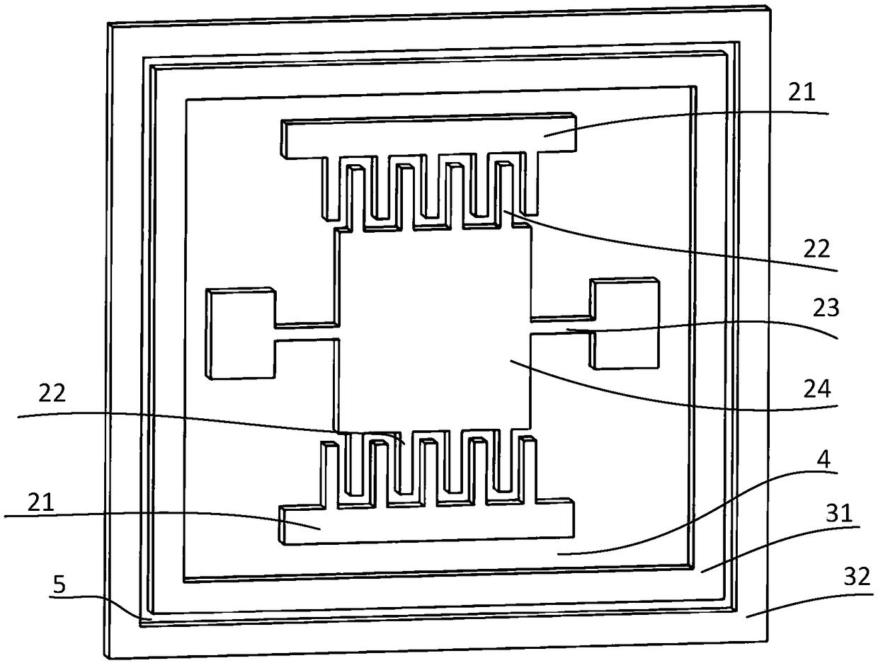
[0031] from figure 2 It can be seen that the driving comb 2 includes a static comb and its anchor point 21, a moving comb 22, a movable mass 24 connected to the moving comb 22, a movable beam supporting the movement of the movable mass 24 and its supporting anchor. Point 23. The pair of movable and static combs is used to drive the mass block 24 to move along a certain direction of the movable b...

Embodiment 2

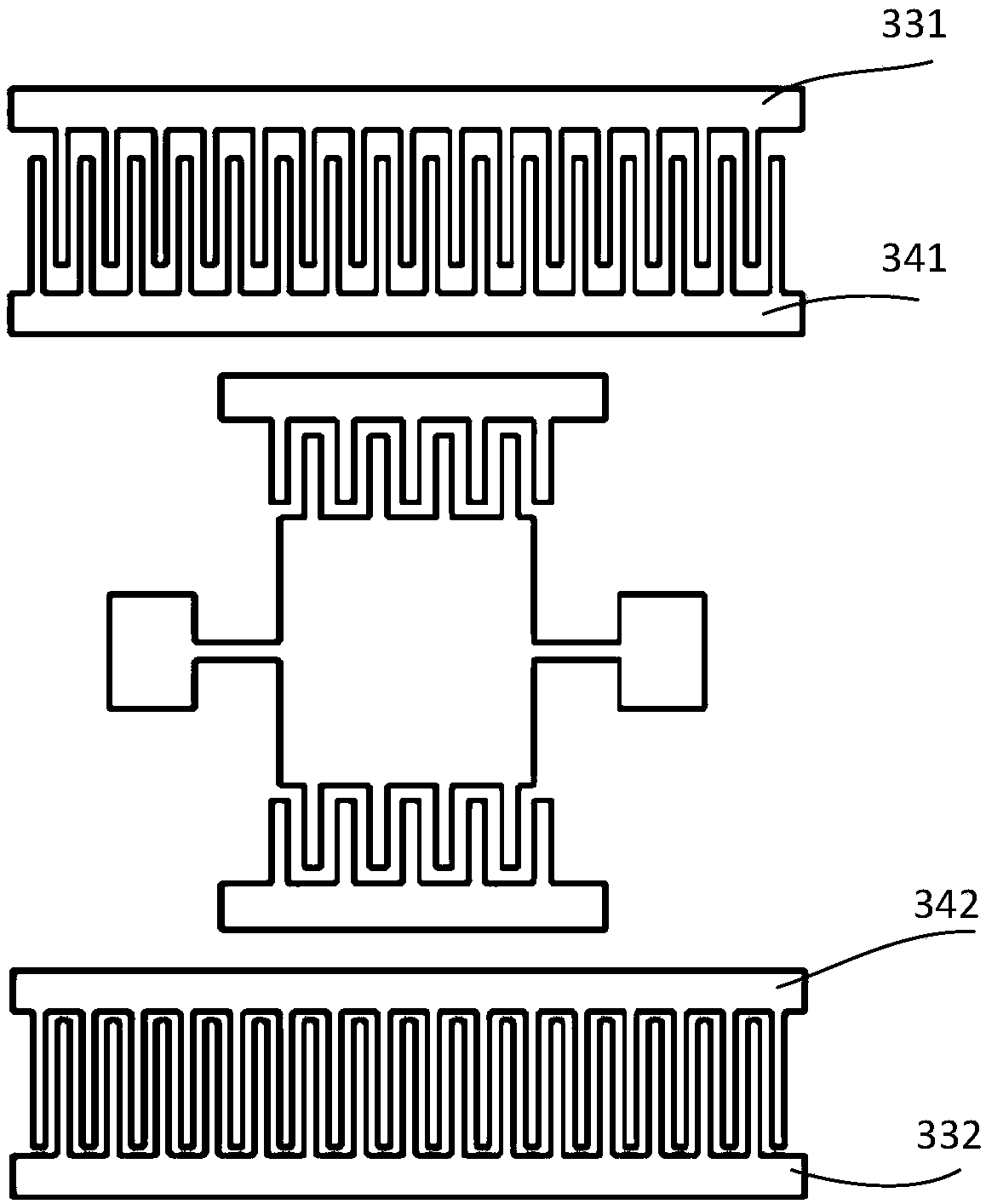
[0035] The shape of the two electrodes in the adsorption electrode electrode pair can be simple linear, wave linear, broken line, or staggered teeth, etc., from image 3 It can be seen that the difference between this embodiment and the first embodiment is that the adsorption electrode 3 in this embodiment includes two pairs of electrodes, and each pair of electrode pairs is a staggered tooth type (comb type), and the third electrode 331 is connected to the fourth electrode pair. The electrode 341, the fifth electrode 332, and the sixth electrode 342 are respectively used as two pairs of adsorption electrodes, and are arranged near the dynamic and static comb pairs of the comb driver to clean the particles. The toothed electrodes can increase the overlapping length of the two electrodes and increase the adsorption The effective adsorption area of ​​the electrode improves the adsorption effect on particulate pollutants.

[0036] The height of the two electrodes of the adsorptio...

Embodiment 3

[0038] The difference between this embodiment and the second embodiment is that the adsorption electrode in this embodiment is a movable structure, such as Figure 5 As shown, the eleventh electrode 371 and the twelfth electrode 381, the thirteenth electrode 372 and the fourteenth electrode 382 are respectively used as adsorption electrode pairs, wherein the eleventh electrode 371 is supported by the first movable beam 61, and the first movable beam 61 The beam 61 is supported by the first support anchor point 71; the thirteenth electrode 372 is supported by the second movable beam 62, and the second movable beam 62 is supported by the second support anchor point 72; The second electrode 381, the thirteenth electrode 372 and the fourteenth electrode 382 apply specific signals to drive the eleventh electrode 371 and the thirteenth electrode 372 to move in a certain direction of the movable beam, and keep the eleventh electrode 371 and the The thirteen electrodes 372 are continu...


PUM


Abstract

The invention belongs to the field of micro-electromechanical systems (MEMS) and relates to a comb driver, in particular to a comb driver with a self-cleaning function. The driver includes a drive comb and an adsorption electrode disposed on a silicon substrate, wherein the adsorption electrode comprises at least one pair of electrodes, one electrode being grounded and the other electrode being connected to a positive or negative level signal; The adsorption electrode and the driving comb teeth are separated by an insulating groove, and the adsorption electrode and the driving comb teeth are both located inside the enclosed housing. The problem of low reliability of the comb drive due to the deposition of particles on the drive comb is solved.

Description

technical field [0001] The invention belongs to the field of microelectromechanical systems (MEMS), and relates to a comb driver, in particular to a comb driver with a self-cleaning function. Background technique [0002] The electrostatic comb driver has a simple structure, high energy density, low power consumption, and the process is easy to integrate with the IC process. It is a commonly used driving form in the MEMS structure. widely used in. [0003] However, the gap between the dynamic and static comb teeth of the electrostatic comb driver is very small, generally at the micron level, and the comb electrode must be powered on during the working process of the driver. After power is applied, the comb teeth are very easy to absorb particles in the working environment, eventually causing short-circuit failure. . Although the electrostatic comb driver device generally needs to be packaged and sealed for use, due to the limitations of the packaging environment, packaging...

Claims


Application Information

Patent Timeline
Patent Type & Authority Applications(China)
IPC IPC(8): H02N2/00
CPCH02N2/001
Inventor 宋秀敏夏长锋何伟乔大勇
Owner XI AN ZHISENSOR TECH CO LTD
Why Eureka
Try Eureka