Device and method for avoiding stall caused by strong wind in vertical axis wind turbine

A wind turbine, vertical axis technology, applied in wind turbine components, control of wind turbines, wind turbines at right angles to the wind direction, etc., can solve problems such as generator stalls, broken blades, etc. Simple, secure results

Inactive Publication Date: 2013-03-13
GUANGZHOU YATU NEW ENERGY TECH
View PDF8 Cites 0 Cited by
  • Summary
  • Abstract
  • Description
  • Claims
  • Application Information

AI Technical Summary

Problems solved by technology

[0003] One of the technical problems to be solved by the present invention is to provide a device for vertical axis wind power generators to avoid stalls caused by strong winds. generator set safety
[0004] The second technical problem to be solved by the present invention is to provide a method for avoiding the stall caused by strong wind of the vertical axis wind power generator. generator set safety

Method used


Image

  • Device and method for avoiding stall caused by strong wind in vertical axis wind turbine
  • Device and method for avoiding stall caused by strong wind in vertical axis wind turbine
  • Device and method for avoiding stall caused by strong wind in vertical axis wind turbine

Examples


Embodiment 1

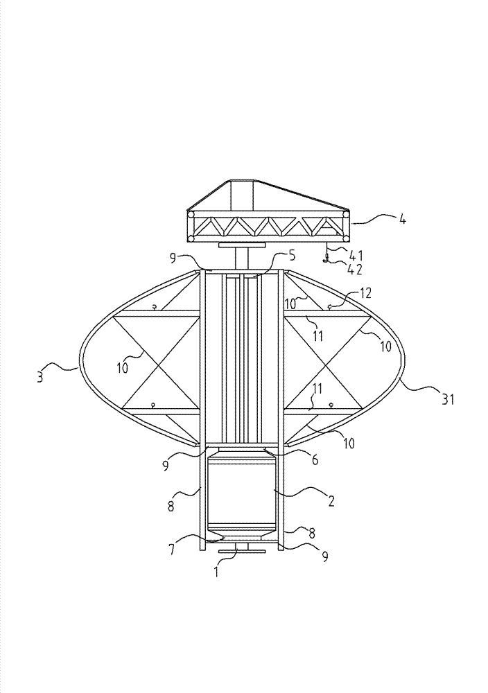
[0038] like figure 1As shown, a device for avoiding a stall caused by strong wind of a vertical axis wind power generator includes a tower column 1 and more than one power generation unit arranged on the tower column 1. In this embodiment, only one A power generation unit, the power generation unit includes a Φ-shaped blade group, an outer rotor generator 2 and a crane 4 .

[0039] like figure 2 As shown, the upper end of the Φ-shaped blade group is provided with a first bearing 5, the inner ring of the first bearing 5 is fixedly sleeved on the tower column 1, and the upper end of the Φ-shaped blade group is connected with the outer ring of the first bearing 5; The lower end of the group is provided with a second bearing 6, the inner ring of the second bearing 6 is fixedly sleeved on the tower column 1, the lower end of the blade group is connected with the outer ring of the second bearing 6, and the blade group is connected to the second bearing 6 through the first bearing ...

Embodiment 2

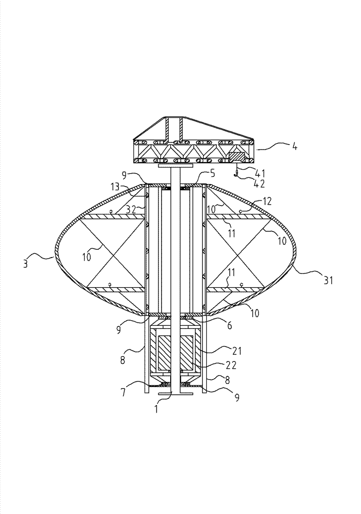
[0046] like Figure 4 As shown, a device for avoiding a stall caused by strong wind of a vertical axis wind power generator includes a tower column 1 and more than one power generation unit arranged on the tower column 1. In this embodiment, the tower column 1 is only provided with two A power generation unit arranged up and down, the power generation unit includes a Φ-shaped blade group, an outer rotor generator 2, and a crane 4.

[0047] like Figure 5 As shown, the upper end of the blade group is provided with a first bearing 5, the inner ring of the first bearing 5 is fixedly sleeved on the tower column 1, and the upper end of the blade group is connected with the outer ring of the first bearing 5; the lower end of the blade group is provided with a second Bearing 6, the inner ring of the second bearing 6 is fixedly sleeved on the tower column 1, the lower end of the blade group is connected to the outer ring of the second bearing 6, and the blade group is pivotally conne...

Embodiment 3

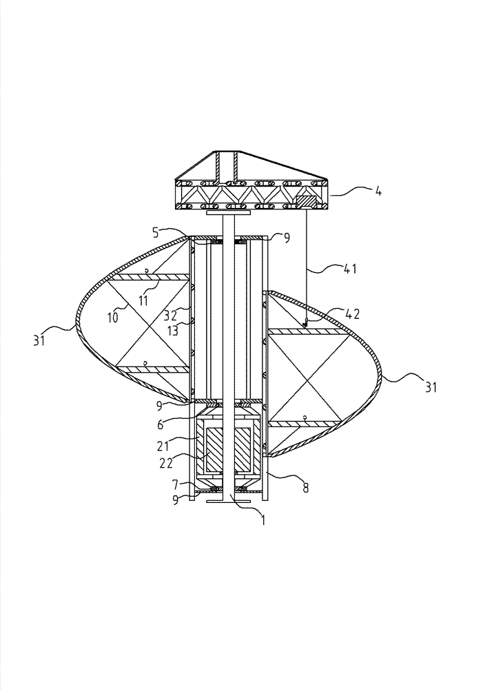
[0054] like Figure 7 As shown, a device for avoiding a stall caused by strong wind of a vertical axis wind power generator includes a tower column 1 and more than one power generation unit arranged on the tower column 1. In this embodiment, the tower column 1 is only provided with two A power generation unit arranged up and down, the power generation unit includes a Φ-shaped blade group, an outer rotor generator 2, and a crane 4.

[0055] like Figure 8 As shown, the upper end of the blade group is provided with a first bearing 5, the inner ring of the first bearing 5 is fixedly sleeved on the tower column 1, and the upper end of the blade group is connected with the outer ring of the first bearing 5; the lower end of the blade group is provided with a second Bearing 6, the inner ring of the second bearing 6 is fixedly sleeved on the tower column 1, the lower end of the blade group is connected to the outer ring of the second bearing 6, and the blade group is pivotally conne...


PUM


Abstract

A device and method for preventing velocity loss during strong wind for vertical-shaft wind power generators. At least one power generating unit is disposed on a tower column (1). A crane (4) is disposed on the top of the tower column. The crane is disposed with a hook (42). A blade assembly comprises at least two blades (3). The blade is bow-shaped and consists of a chord-shaped part (32) and a corresponding arc-shaped part (31). At least one supporting arm (11) is disposed between the chord-shaped part and the arc-shaped part. Multiple lift lugs (12) onto which the hook hangs are disposed on the supporting arm. At least two rollers (13) are disposed on the chord-shaped part. Tracks (8) are disposed in each power generating unit, the number of the tracks being equal to the number of blades. The tracks are synchronous to the blades. The arc-shaped part and the rollers form a sliding mechanism that is complementary to the movement of the tracks. The upper end and the lower end of the blade are disposed with male connecting mechanisms. Female connecting mechanisms are disposed on the track at positions corresponding to the upper end and the lower end of the blade. The male connecting mechanisms and the female connecting mechanisms complement each other. During strong winds, the crane lowers the blades onto the ground in the order from the bottom to the top. The device is easy to operate and solves the problems of velocity loss of power generators and blade breakage during strong wind and typhoon, thereby ensuring the safety of the power generators.

Description

technical field [0001] The invention relates to a vertical axis wind power generator, in particular to a device and a method capable of causing the generator to stall due to strong wind. Background technique [0002] The main function of the wind turbine brake mechanism has two aspects: one is to fix the blades of the wind turbine when the equipment is overhauled, and the other is to avoid damage to the wind turbine when the wind is particularly strong or typhoon. Fixed and not rotated. The braking methods of existing wind-driven generators mainly include mechanical braking mechanisms and pitch-variable braking systems. The mechanical braking mechanism is generally a hydraulic braking mechanism composed of a brake disc, a brake block and a hydraulic control device. The brake disc of this type of braking mechanism is fixed on the main shaft of the motor unit, and the brake block is controlled by the hydraulic control device. When encountering a particularly strong wind or t...

Claims


Application Information

Patent Timeline
Patent Type & Authority Patents(China)
IPC IPC(8): F03D11/00B66C23/18F03D3/06F03D9/00
CPCB66C23/207F03D3/062F03D7/06F05B2240/916F05B2270/107Y02E10/728Y02E10/74
Inventor 邓允河
Owner GUANGZHOU YATU NEW ENERGY TECH
Why Eureka
Try Eureka