Laser multiple degrees of freedom precision measurement system based on telescope system

A telescopic system and precision measurement technology, applied in the field of laser multi-degree-of-freedom precision measurement systems, can solve the problems of multi-degree-of-freedom error magnification limitation and difficulty in obtaining, and achieve the effects of simple structure, convenient installation and adjustment, and fewer optical components.

Inactive Publication Date: 2011-11-23
UNIV OF SCI & TECH OF CHINA
View PDF3 Cites 9 Cited by
  • Summary
  • Abstract
  • Description
  • Claims
  • Application Information

AI Technical Summary

Problems solved by technology

These methods use non-contact measurement, low electromagnetic interference, compact structure, and high measurement accuracy, but the magnification of multi-degree-of-freedom errors is limited by the principle, and it is difficult to obtain greater improvement

Method used


Image

  • Laser multiple degrees of freedom precision measurement system based on telescope system
  • Laser multiple degrees of freedom precision measurement system based on telescope system
  • Laser multiple degrees of freedom precision measurement system based on telescope system

Examples


Embodiment 1

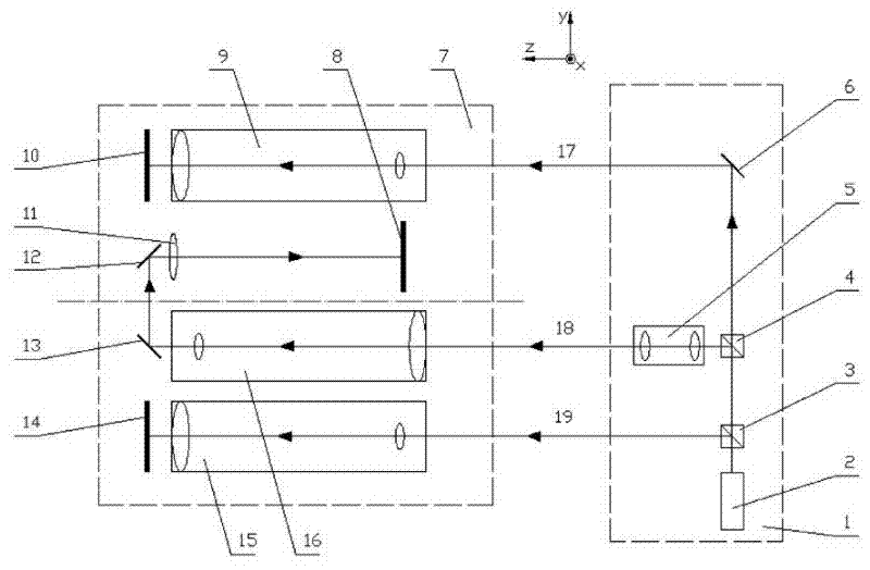
[0027] see figure 1 , the laser multi-degree-of-freedom precision measurement system based on the telescopic system includes a fixed mechanism and a moving mechanism. The moving mechanism 1 is fixed on the kinematic pair of the guide rail, and moves along the linear guide rail with the kinematic pair, and the fixing mechanism 7 is fixed on one end of the measuring guide rail.

[0028] The moving mechanism 1 includes a laser 2 , a first beam splitter 3 , a second beam splitter 4 and a third reflector 6 arranged in sequence, the transmission port of the first beam splitter 3 and the entrance port of the second beam splitter 4 Correspondingly, the transmission port of the second beam splitter 4 corresponds to the incident port of the third reflector 6 ; a laser collimating telescope 5 is provided corresponding to the reflection port of the second beam splitter 4 . Both the first beam splitter 3 and the second beam splitter 4 divide the incident beam into two beams of reflected l...

Embodiment 2

[0031] The difference from Embodiment 1 is that the first measuring telescopic mechanism 15 , the second measuring telescopic mechanism 16 and the third measuring telescopic mechanism 9 are Galilean telescope systems; the lens 11 is a composite lens.

[0032] All the other structures are with embodiment 1.

Embodiment 3

[0034] The difference from Embodiment 1 is that the first photoelectric receiver 14, the second photoelectric receiver 8 and the third photoelectric receiver 10 adopt a charge-coupled device (CCD), and the first reflector 13, the second reflector 12 and the third The reflector 6 adopts a folding prism.

[0035] All the other structures are with embodiment 1.

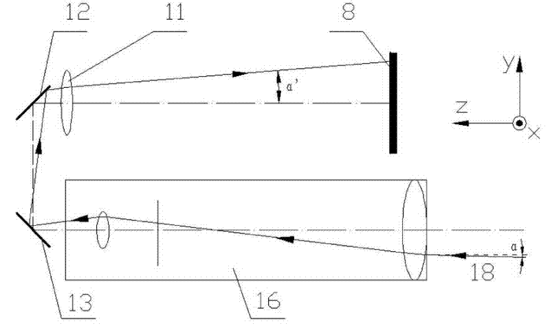
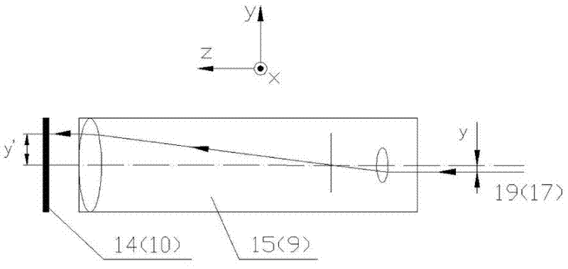
[0036] see figure 2 , image 3 , Figure 4 , explaining the principle and method of measuring the five-degree-of-freedom error:

[0037] Assume that initially, the posture of the moving part of the linear guideway makes the first laser beam 19, the second laser beam 18 and the third laser beam 17 respectively correspond to the first measuring telescopic mechanism 15, the second measuring telescopic mechanism 16 and the third measuring telescope. The optical axes of the far mechanism 9 coincide.

[0038] The highly stable laser beam emitted by the laser 2 passes through the first beam splitter 3 and is split by the ...


PUM


Abstract

The invention relates to a laser multiple degrees of freedom precision measurement system based on a telescope system. The system comprises a moving mechanism and a fixed mechanism, and the moving mechanism generates three beams of parallel light; the fixed mechanism comprises a first measurement telescope mechanism, a second measurement telescope mechanism and a third measurement telescope mechanism which are arrayed in parallel; entrance ports of the three measurement telescope mechanisms respectively correspond to the three beams of parallel light which are emitted by the moving mechanism; exit ports are correspondingly provided with photoelectric receivers; and two reflectors and a lens are sequentially arranged between the exit port and the photoelectric receiver of the second measurement telescope mechanism. The system provided by the invention is used for measuring two straightness errors and three angle errors which are vertical to the proceed direction, and the light path adjustment is simple; less optical devices are used in the system, the system has the advantages of simple structures and small size is convenient for installation and adjustment, and the rapid measurement with high accuracy can be obtained; and the system can also finish six-degree-of-freedom full posture measurement together with length measuring technology such as a laser interferometer.

Description

technical field [0001] The invention belongs to the technical field of high-precision measurement of the multi-degree-of-freedom error or motion attitude of an object when it moves along a linear guide rail, and specifically relates to a laser multi-degree-of-freedom precision measurement system based on a telescopic system. Background technique [0002] In many fields such as machinery manufacturing, machining, measurement, control, etc., linear guide rails or one-dimensional translation stages are widely used. There are six errors in the linear guide. Except for the positioning error, the other five are geometric errors, which are pitch angle, yaw angle, roll angle, and two straightness perpendicular to the direction of travel. With the improvement and development of the technical level, the demand for the accuracy of the guide rail is getting higher and higher, and the detection requirements for the multi-degree-of-freedom error of the guide rail are also getting higher a...

Claims


Application Information

Patent Timeline
Patent Type & Authority Applications(China)
IPC IPC(8): G01B11/26G01B11/27
Inventor 王克逸闫佩正吴朔郝鹏曹兆楼
Owner UNIV OF SCI & TECH OF CHINA
Why Eureka
Try Eureka