
Testing method of vortex-induced vibration of cylinder

A technology of vortex-induced vibration and test method, which is applied in fluid dynamics test, vibration test, machine/structural component test, etc. Fluid-solid coupling characteristics of large-displacement vortex-induced vibration of pipes, and the inability to reveal the essential characteristics of vortex-induced lift and drag forces

Inactive Publication Date: 2011-11-23
OCEAN UNIV OF CHINA
View PDF4 Cites 25 Cited by
  • Summary
  • Abstract
  • Description
  • Claims
  • Application Information

AI Technical Summary

Problems solved by technology

[0013] 1. The one-way vortex-induced vibration test in the direction of flow or in the transverse direction cannot be carried out. Therefore, the experimental research on the influence of the flow (transverse) vibration of the elastic cylinder on the vortex-induced vibration in the transverse (flow) direction cannot be realized, and the elastic cylinder cannot be revealed. The essential characteristics of the influence of fluid-solid coupling in the downstream (transverse) direction on vortex discharge, vortex-induced lift and drag force cannot reveal the fluid-solid coupling characteristics of downstream and lateral coupled vibrations and their influence on vortex-induced vibrations
[0014] 2. The fluid-solid coupling characteristics of large displacement vortex-induced vibration of deep water risers cannot be simulated. Large displacement means geometric nonlinearity, and the assumption of small linear displacement is no longer applicable. Therefore, the existing vortex-induced vibration test technology is not suitable for those with strong geometric nonlinearity. Experimental research on vortex-induced vibration of linear deepwater riser

Method used


Image

  • Testing method of vortex-induced vibration of cylinder
  • Testing method of vortex-induced vibration of cylinder
  • Testing method of vortex-induced vibration of cylinder

Examples


Embodiment Construction

[0033] The present invention will be described in detail below in conjunction with the accompanying drawings and specific embodiments.

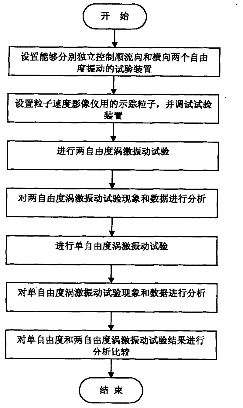
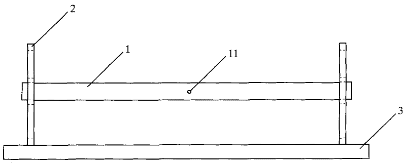
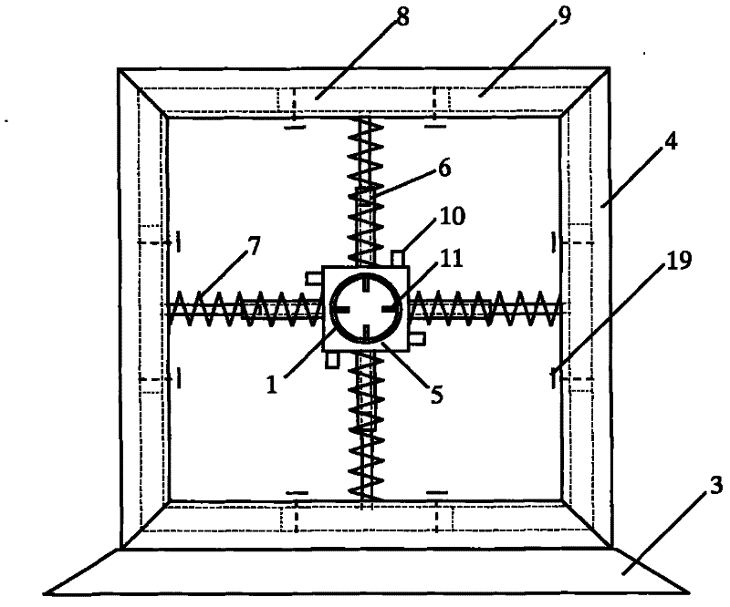
[0034] The vortex-induced vibration of the cylinder includes the vibration of two degrees of freedom in the direction of flow and in the transverse direction. The mutual influence of vibration, to study the fluid-solid coupling effect of flow-direction and transverse vortex-induced vibration and its influence on vortex-induced vibration, the test device should be able to control the flow-direction or lateral vibration respectively, that is, constrain the flow-direction or lateral vibration, so that the test model Only for lateral or downstream vibration. During the test, the hydrodynamic pressure acting on the cylinder and the vibration parameters of the cylinder are measured synchronously through the pressure sensor and the acceleration sensor installed on the test model. The morphology of the wake field was recorded synchronously by the Pa...


PUM


Abstract

The invention relates to a testing method of vibration of a structure in a flow field, in particular to the testing method of vortex-induced vibration of a cylinder. In the method, a testing device which can independently control the two-degree-of-freedom vibration along the flow direction and the transverse direction respectively is utilized for performing two-degree-of-freedom vortex-induced vibration testing and single-degree-of-freedom vortex-induced vibration testing respectively, analyzing phenomena and data of the two-degree-of-freedom vortex-induced vibration testing and the single-degree-of-freedom vortex-induced vibration testing and comparing analysis results of the single-degree-of-freedom vortex-induced vibration testing and the two-degree-of-freedom vortex-induced vibration testing. Under the same testing conditions, the single-degree-of-freedom vortex-induced vibration testing along the flow direction or the transverse direction and the two-degree-of-freedom vortex-induced vibration testing along the flow direction or the transverse direction can be completed and synchronous measurement of hydrodynamic pressure, motion parameters (displacement, speed and acceleration) of a testing model and vortex discharge can be realized.

Description

technical field [0001] The invention relates to a test method for structure vibration in a flow field, in particular to a test method for vortex-induced vibration of a cylinder. Background technique [0002] Vortex-induced vibration is a special vibration form of a cylinder in the flow field, and it is the vibration caused by the vortex shedding at the wake of the cylinder. The research on vortex-induced vibration has a history of more than 60 years, but in recent years, the riser vortex-induced vibration problem caused by the development of deep-water oil and gas in the ocean has set off a new round of cylinder vortex-induced vibration research upsurge. [0003] The study found that the special vortex-induced vibration phenomenon of deepwater risers cannot be well explained by the existing vortex-induced vibration theory, such as large vibration amplitude. The existing vortex-induced vibration theory believes that the amplitude A of vortex-induced vibration is related to th...

Claims


Application Information

Patent Timeline
IPC IPC(8): G01M7/06G01M10/00
Inventor 黄维平周阳孙铭远刘震段金龙范杰利
Owner OCEAN UNIV OF CHINA
Learn More