
PDA detector holding device

A clamping device and detector technology, which is applied in the direction of measuring devices, instruments, scientific instruments, etc., can solve problems such as small locking surface, easy loosening of locking screw 6, and influence on the stability of instrument measurement accuracy, so as to reduce maintenance work Quantity, reduce maintenance cost, increase the effect of locking force

Inactive Publication Date: 2011-11-23
安徽蓝盾光电子股份有限公司
View PDF5 Cites 1 Cited by
  • Summary
  • Abstract
  • Description
  • Claims
  • Application Information

AI Technical Summary

Problems solved by technology

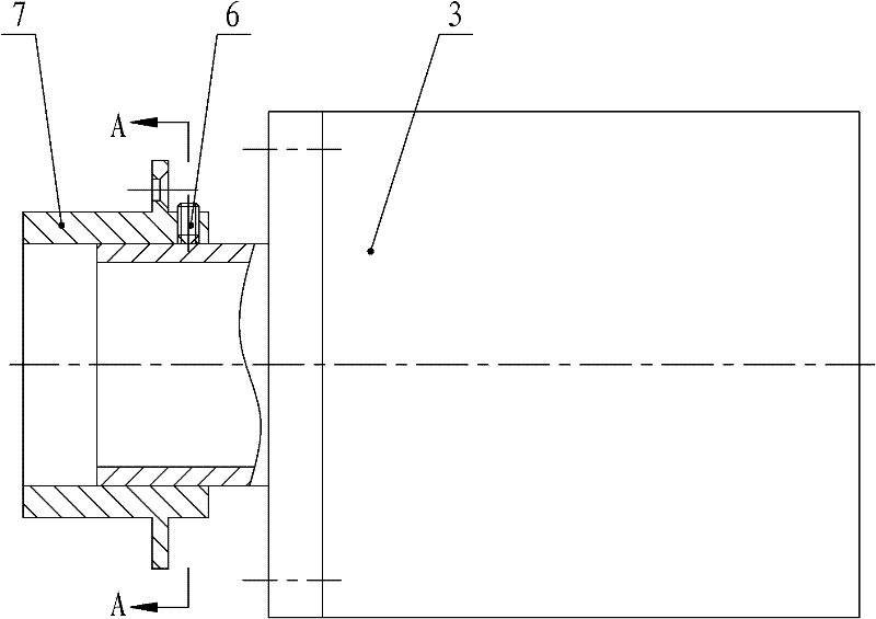
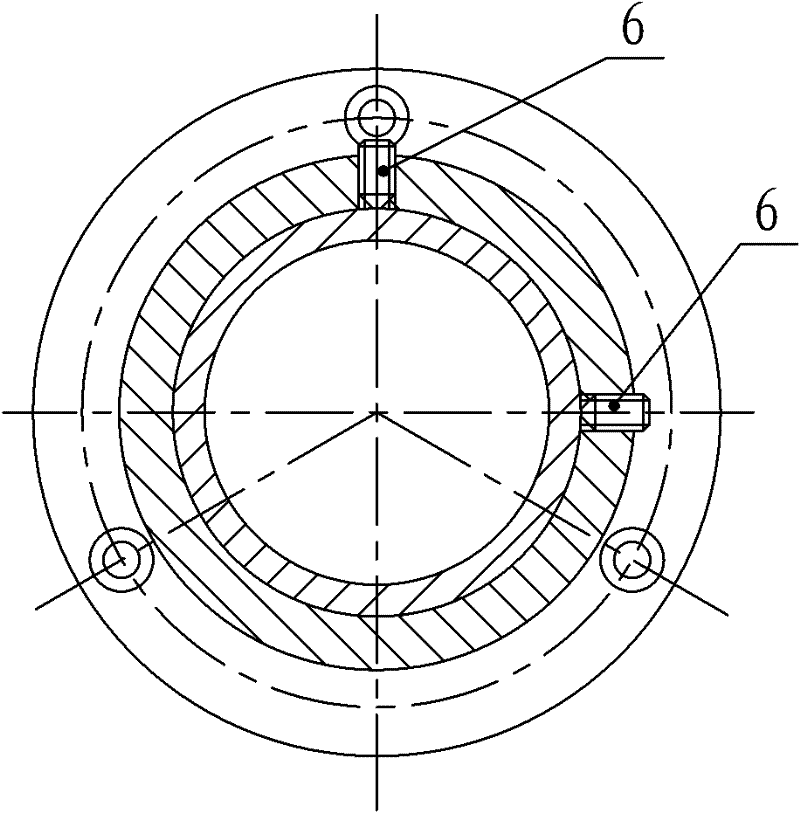
[0004] The locking method of the traditional PDA detector is unreasonable, such as figure 1 , 2 As shown, the connecting shaft of the PDA detector is inserted into the locking device 7, and is directly locked by two locking screws 6, that is, the original locking method is a two-point locking type, and the locking surface is small
This locking method has the following serious disadvantages. One, when the instrument is running, the locking screw 6 is easy to loosen, so that the PDA detector 3 is shifted, and the optical signal received by the PDA detector is attenuated to affect the measurement accuracy; Second, the two locking screws 6 will each print a pit on the connecting shaft of the PDA detector. When the PDA detector needs to be fine-tuned again and locked again, the PDA detector will easily return to the last time it was fixed. It is difficult to realize the fine-tuning function due to the positions of the two pressure pits. Because the PDA detector does not get the best light intensity signal, the measurement accuracy and operation stability of the instrument are seriously affected; Work load and maintenance cost

Method used


Image

  • PDA detector holding device
  • PDA detector holding device
  • PDA detector holding device

Examples


Embodiment Construction

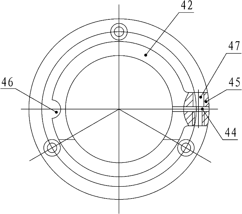
[0028] Such as Figure 3-6 As shown, the clamping device is cylindrical, one end of the clamping device is a fixed end 41 connected with the spectrometer 2, and the other end is a clamped end 42 connected with the PDA detector 3, and the connection fixed end of the clamping device is 41 and the clamping end 42 are provided with missing parts 43 on the cylinder body, and the missing parts 43 are distributed along the circumferential direction of the clamping device. Open slot 44 .

[0029] The notch 43 makes the clamping end 42 have good elasticity; the opening groove 44 can adjust the clamping force.

[0030] The opening groove 44 is arranged on the side where the clamping end 42 is located at the missing part 43, and the parts of the clamping end 42 located on both sides of the opening groove 44 are provided with flanges 45 protruding to the outside of the clamping device. Corresponding through holes 47 are provided on the side 45 .

[0031] The flange 45 avoids direct con...


PUM


Abstract

The invention relates to the field of PDA detector, specifically relates to a PDA detector holding device. The PDA detector holding device is tubular. One end of the holding device is the fixing end connected with a spectrometer, the other end of the holding device is the holding end connected with a PDA detector. A gap portion is arranged on the tubular holding device, wherein the position of the gap portion is the connection of the fixing end and the holding end, and is distributed along a circumference of the holding device. An open slot penetrating the holding device is arranged on the holding end along an axial direction of the holding device. With the present invention, the traditional two-point locking mode is changed into a circumferential surface locking mode so as to raise the locking force; the screw press pit is no longer generated on the PDA detector; adjusting and fixing can be conveniently performed again to realize fine adjustment function of the PDA detector; the shift phenomenon of the PDA detector during operating is thoroughly solved; maintenance workload and maintenance cost are substantially reduced, stability of the device operating is improved, measurement precision of the device is raised.

Description

technical field [0001] The invention relates to the field of PDA detectors, in particular to a PDA detector clamping device. Background technique [0002] Differential Optical Absorption Spectroscopy (DOAS, Differential Optical Absorption Spectroscopy) measurement technology is based on the characteristic absorption characteristics of trace pollution components in the air to ultraviolet and visible light bands, and measures the environment through the identification of characteristic absorption spectra by PDA detectors. The type and concentration of polluting gases in the air, such as SO 2 , NO 2 , O 3 Wait. DOAS gas analyzer is an important instrument in the field of air pollution measurement in my country that adopts the above-mentioned measurement technology. [0003] Since the DOSA gas analyzer was introduced to the market, it has been favored and praised by the majority of users. In order to increase the intensity of the light signal when used in the field, it is n...

Claims


Application Information

Patent Timeline
IPC IPC(8): G01N21/01G01N21/33G01N21/31
Inventor 潘焕双
Owner 安徽蓝盾光电子股份有限公司
Learn More