Current detector

A current detector and current technology, applied in the direction of voltage/current isolation, instruments, measuring devices, etc., to achieve the effects of improving safety, reducing delay factors, and improving responsiveness

Active Publication Date: 2011-11-23
TAMURA KK
View PDF6 Cites 22 Cited by
  • Summary
  • Abstract
  • Description
  • Claims
  • Application Information

AI Technical Summary

Problems solved by technology

However, when the detected current changes greatly at a certain time, such as instantaneous overcurrent, due to the delay factor in the magnetic

Method used


Image

  • Current detector
  • Current detector
  • Current detector

Examples


Embodiment Construction

[0028] Hereinafter, embodiments of the present invention will be described with reference to the drawings.

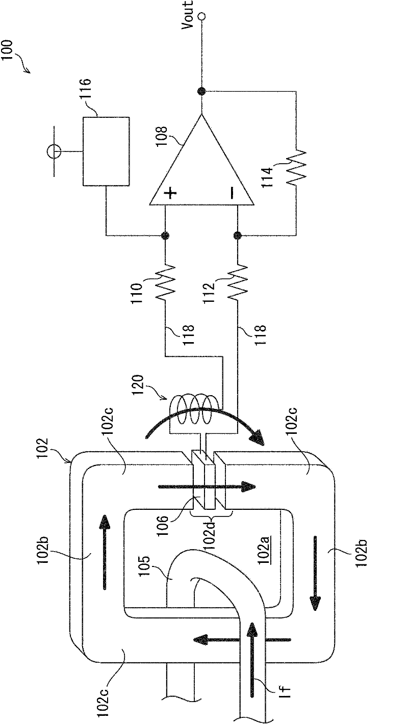
[0029] figure 1 It is a schematic diagram showing the structure of the current detector 100 of one embodiment. Next, the configuration of the current detector 100 will be described.

[0030] [magnetic core]

[0031] The current detector 100 includes, for example, a ferrite core 102 . The magnetic core 102 has a substantially square annular shape (annular shape) as a whole. A substantially rectangular current conducting portion 102 a is formed inside the magnetic core 102 (inner circumference of the ring). A conductor 105 such as a bus is inserted through the current conducting portion 102a. The current detector 100 detects the current flowing through the conductor 105 . The magnetic core 102 is arranged in a ring shape along the direction of the magnetic field generated when the detected current (If) flows through the conductor 105 . Also, when the detected curre...


PUM


Abstract

The invention provides a current detector (100), which comprises a ring-shaped magnetic core (102) arranged at the periphery of a conductor (105) being conducted by a current to be detected, a hall element (106) arranged in the gap (102d) of the magnetic core (102), an amplifier (108) for amplifying voltage signals outputted by the hall element (106) and an electromagnetic induction part (120) formed on a signal path (118).If the current to be detected changes, the electromagnetic induction part (120) will generate an induction electromotive force so as to improve the detection response.

Description

technical field [0001] The invention relates to a magnetic proportional current detector used for current measurement or overcurrent detection, current feedback control and the like. Background technique [0002] This current detector (current sensor) adopts the following method: through the magnetic core (core), the magnetic flux generated by conducting the detected current is collected, and then the Hall element is used to convert the magnetic flux into a voltage signal to detect the current. value. In addition, the output voltage obtained from the Hall element is amplified by an amplifier such as an operational amplifier, and used as a detection signal of the sensor. [0003] In general, the output voltage of the Hall element is proportional to the magnitude (magnetic flux) of the magnetic field passing through the core gap (magnetically sensitive portion of the Hall element). However, since the magnetic flux passing outside the magnetic sensitive part of the Hall eleme...

Claims


Application Information

Patent Timeline
IPC IPC(8): G01R15/00G01R15/20
Inventor 龙末洋
Owner TAMURA KK
Why Eureka
Try Eureka