
Method for testing RCS (radar cross section) of low-scattering conformal antenna based on two-dimensional microwave imaging

A conformal antenna and microwave imaging technology, applied in the microwave field, can solve problems such as indistinguishability, and achieve good results and large-scale project promotion value

Inactive Publication Date: 2011-11-23
NORTHWESTERN POLYTECHNICAL UNIV
View PDF0 Cites 25 Cited by
  • Summary
  • Abstract
  • Description
  • Claims
  • Application Information

AI Technical Summary

Problems solved by technology

[0008] 1) The antenna is embedded in the body structure, which brings new problems to the conventional RCS test and is difficult to distinguish;

Method used


Image

  • Method for testing RCS (radar cross section) of low-scattering conformal antenna based on two-dimensional microwave imaging
  • Method for testing RCS (radar cross section) of low-scattering conformal antenna based on two-dimensional microwave imaging
  • Method for testing RCS (radar cross section) of low-scattering conformal antenna based on two-dimensional microwave imaging

Examples


Embodiment Construction

[0033] Now in conjunction with embodiment, accompanying drawing, the present invention will be further described:

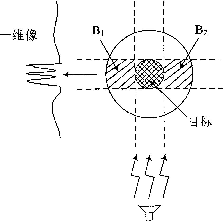
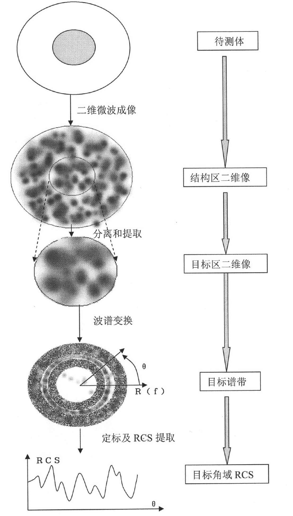
[0034] Such as Figure 5 As shown in , to measure the conformal antenna in the installed state, the two-dimensional microwave imaging system used is as follows Figure 6 As shown, the system transmits a step frequency signal, the signal is amplified by the power amplifier and then transmitted directly by the standard gain antenna, and the echo signal is sent to the receiving end of the vector network analyzer through another standard gain antenna that is very close to each other, the turntable rotates, and the Acquire echo data at a certain angle interval for two-dimensional imaging.

[0035] The experimental measurement steps are as follows:

[0036] 1) Measure the empty dark room and perform time-domain cancellation to reduce the influence of clutter.

[0037] 2) Measure the target, transform it into the time domain, use the range gate to intercept the targe...


PUM


Abstract

The invention relates to a method for testing an RCS (radar cross section) of a low-scattering conformal antenna based on two-dimensional microwave imaging, which is characterized by comprising the following steps: carrying out an RCS test on a metal envelope and a low-scattering conformal antenna in an installed state so as to obtain a two-dimensional microwave image; carrying out two-dimensional Fourier transform on the obtained new two-dimensional microwave image so as to obtain the data of a target spectral domain; carrying out an RCS test on a metal ball (the RCS of the metal ball is known) so as to obtain a two-dimensional microwave image, then carrying out two-dimensional Fourier transform on the obtained two-dimensional microwave image so as to obtain the data G0 (f, theta) of a scattered field of the metal ball, wherein the data of the scattered field varies with frequency and angle; and finally, obtaining the RCS of the conformal antenna, wherein the RCS of the conformal antenna meets the following formula: RCS= G1 (f, theta) (of the conformal antenna) - G0 (f, theta) (of the metal ball) + RCS (of the metal ball). The method provided by the invention is a method for testing an RCS (radar cross section) of a low-scattering conformal antenna in an installed state based on the two-dimensional microwave imaging technology, and after practicing, the obtained effect is good, therefore, the method provided by the invention has great engineering popularization value.

Description

technical field [0001] The invention relates to a low-scattering conformal antenna RCS testing method based on two-dimensional microwave imaging, which uses two-dimensional microwave imaging technology to separate and extract the RCS of the conformal antenna in an installed state. This is a new method for RCS measurement of low-scattering targets, which belongs to the field of microwave technology. Background technique [0002] Radar is an effective long-range detection device. It accurately locates by emitting electromagnetic waves and receiving the echoes reflected by the target. The size of the echoes received by the radar is related to the effective cross-sectional area of ​​the target. We call this effective cross-sectional area radar Scattering Cross Section (RCS for short). [0003] With the rapid development of electronic warfare, the large-scale use of stealth weapons is a prominent feature of modern warfare. For example, the third-generation stealth fighter F-117...

Claims


Application Information

Patent Timeline
IPC IPC(8): G01S7/41G01S7/40
Inventor 李南京郭淑霞胡楚锋刘宁刘琦李瑛陈卫军杨博张麟兮王保平
Owner NORTHWESTERN POLYTECHNICAL UNIV
Learn More