Automatic upright metallurgical microscope

A metallographic microscope, upright technology, applied in the field of microscopes, can solve the problems of inability to realize free conversion and automatic focusing of objective lenses, expensive electric control equipment, expensive equipment, etc., to achieve automatic focusing, convenient focusing operation, Cost-effective effect

Inactive Publication Date: 2011-11-23
GUILIN UNIV OF ELECTRONIC TECH
View PDF6 Cites 13 Cited by
  • Summary
  • Abstract
  • Description
  • Claims
  • Application Information

AI Technical Summary

Problems solved by technology

[0004] 1. Although the brightness of the light source is adjustable, it lacks an intuitive brightness display
[0005] 2. Workbench X, Y, Z have certain electric control, but the free conversion and automatic focus of the objective lens cannot be realized
[0006] The electric control equipment used is expensive and the technology is complex, resulting in expensive equipment

Method used


Image

  • Automatic upright metallurgical microscope
  • Automatic upright metallurgical microscope
  • Automatic upright metallurgical microscope

Examples


Embodiment Construction

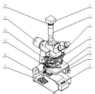
[0020] See figure 1 combine figure 2 .

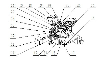
[0021] A CCD1 is set on the top of the lens barrel 2, under the CCD1 is a CCD interface 14, and the workbench is an X-direction platen 11 and a Y-direction platen respectively controlled by an X-direction stepping motor 3, a Y-direction stepping motor 7, and a Z-direction stepping motor 10. 5. The three-axis linkage workbench composed of the Z-direction platen 6, the objective lens is installed on the objective lens converter 4 controlled by the W-axis stepping motor 28, and the single-chip microcomputer 9 that can receive PC instructions and process and digitally adjust the light source is set on in the circuit board inside the microscope.

[0022] The main function of the electric adjustment mechanism in the X, Y, and Z directions of the workbench is to automatically adjust the focus. The control mechanism includes a three-axis linkage workbench, an X-direction stepping motor 3, a Y-direction stepping motor 7, a Z-direction steppi...


PUM


Abstract

The invention provides an automatic upright metallurgical microscope. The microscope provided by the invention comprises a drawtube, a handel, a workbench, an objective lens, a light source base and a circuit board, wherein a CCD (Charge Coupled Device) interface is arranged on the top of the drawtube; the workbench is a three-axis linked workbench consisting of an X-directional soleplate, a Y-directional soleplate and a Z-directional soleplate which are respectively controlled by an X-directional step motor, a Y-directional step motor, a Z-directional step motor; the objective lens is arranged on an objective lens converter controlled by a W-axial step motor; and a singlechip circuit capable of receiving and processing a PC (personal computer) command and digitally adjusting a light source is arranged in a circuit board in the microscope. The automatic upright metallurgical microscope can be used for performing position control on an objective table and position detection on the objective lens converter through controlling the X, Y and Z directional electric adjustment of the workbench and the electric switching of the lens by a computer, and can meet the requirements of remote network experiments by displaying images collected by a digital CCD on the computer.

Description

technical field [0001] The invention relates to a microscope, in particular to an automatic upright metallurgical microscope. Background technique [0002] At present, the traditional automatic upright metallurgical microscope structure is composed of diopter adjustment ring, eyepiece, zoom regulator, focusing handwheel, reflective illuminator, objective lens, locking handwheel, workbench, microscope base, transmitted light seat , Reflector adjustment knob composition. Put the metallographic sample on the workbench, adjust the brightness of the light source, turn the zoom adjuster to convert the magnification of the objective lens, and rotate the focusing handwheel to manually adjust the focus. After the focus is clear, the surface structure and organization of the metallographic sample can be observed form. [0003] The current automatic upright metallurgical microscope has the following problems: [0004] 1. Although the brightness of the light source is adjustable, it ...

Claims


Application Information

Patent Timeline
Patent Type & Authority Applications(China)
IPC IPC(8): G02B21/00G02B21/24G02B21/06
Inventor 萧泽新邓仕超于新业孟庆新肖华鹏赵莹莹柴华昕张雪飞李鹏肖冉
Owner GUILIN UNIV OF ELECTRONIC TECH
Why Eureka
Try Eureka