Colour forming device, manufacturing method thereof, electronic product and vehicle

A manufacturing method and color-generating technology, applied in nonlinear optics, instruments, optics, etc., can solve the problems of high production cost and application limitations, and achieve the effects of low production cost, wide application, and rich and diverse color changes.

Active Publication Date: 2014-02-19
METAL INDS RES & DEV CENT
View PDF4 Cites 0 Cited by
  • Summary
  • Abstract
  • Description
  • Claims
  • Application Information

AI Technical Summary

Problems solved by technology

This known color-changing element must include two transparent conductive film electrodes as the counter electrode, and it is only applied to transparent non-conductors such as glass substrates, and the appearance of the color is only blue when energized and transparent when no energized, so making High cost and very limited application

Method used


Image

  • Colour forming device, manufacturing method thereof, electronic product and vehicle
  • Colour forming device, manufacturing method thereof, electronic product and vehicle
  • Colour forming device, manufacturing method thereof, electronic product and vehicle

Examples


Embodiment Construction

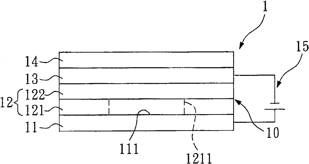
[0045] figure 1 A schematic diagram showing the first embodiment of the color generating device of the present invention. In this embodiment, the chromogenic device 1 includes a body 11, a chromogenic layer 10, a transparent conductive oxide thin film (TCO) 13, a transparent protective layer (such as a polymer layer) 14 and a power supply 15. The body 11 is an opaque conductor and has a surface 111 . The surface 111 of the body 11 has a set roughness (Ra), and the set roughness is preferably between 0.2 μ to 0.5 μ. Preferably, the body 11 is made of stainless steel. More preferably, the surface 111 is a polished mirror surface, which can further enhance the color and gloss performance of the color generating device 1 .

[0046] The chromogenic layer 10 includes at least one composite chromogenic layer 12 , and each composite chromogenic layer 12 includes a chromogenic oxide layer 121 and an ion storage layer 122 . The chromogenic layer 10 is disposed on the surface 111 . ...


PUM


Abstract

The invention relates to a colour forming device, a manufacturing method thereof, an electronic product and a vehicle. The colour forming device comprises a body, a colour forming layer, a transparent conducting layer and a power supply. The body is an opaque conductor having one surface. The colour forming layer is arranged on the surface, wherein the colour forming layer includes at least one composite colour forming layer. The transparent conducting layer is arranged on the colour forming layer. The power supply is electrically connected to the body and the transparent conducting layer and used for controlling the colour forming layer so that the colour forming device produces change of colour. The colour forming device does not need to include two transparent conductive film electrodes as a counter electrode and can be used in electronic products or vehicles, so that the colour forming device has low manufacturing cost, wider application range and various and invertible colour change, thereby realizing the presentation of different functional patterns.

Description

technical field [0001] The present invention relates to a color-generating device and its manufacturing method as well as electronic products and vehicles including the color-generating device. Electronic products and vehicles for color-generating devices. Background technique [0002] In the known technology, the production of the coating color on the surface of the workpiece can be divided into dry sputtering and wet process and other production methods. Among them, in the known dry sputtering process technology, it is better in terms of process, environmental protection and control stability, and is widely used. Known methods of making decorative coatings by physical vapor deposition (Physical Vapor Deposition, PVD) sputtering process, all focus on coating structures such as functional coating or color configuration. Others, such as plastic 3C shells, etc., some require replaceable shells to change the appearance of the decoration. [0003] Relevant known processes suc...

Claims


Application Information

Patent Timeline
Patent Type & Authority Patents(China)
IPC IPC(8): G02F1/153
Inventor 庄道良黄建龙华振宇
Owner METAL INDS RES & DEV CENT
Why Eureka
Try Eureka