Method for optimizing coherent factor of photoetching machine lighting system

A technology of coherence factor and lighting system, applied in the field of coherence factor optimization of lithography machine lighting system, can solve the problems of large amount of calculation, low precision, difficulty in finding the optimal coherence factor, etc., and achieve the effect of small amount of calculation

Active Publication Date: 2011-11-23
BEIJING INSTITUTE OF TECHNOLOGYGY
View PDF4 Cites 0 Cited by
  • Summary
  • Abstract
  • Description
  • Claims
  • Application Information

AI Technical Summary

Problems solved by technology

The prior art (W.N.Partlo, et al.Optimizing NA and Sigma for Sub-Half Micrometer Lithography.Proc.of SPIE1993(1927)) discloses a method of traversing in the variable range of the coherence factor according

Method used


Image

  • Method for optimizing coherent factor of photoetching machine lighting system
  • Method for optimizing coherent factor of photoetching machine lighting system
  • Method for optimizing coherent factor of photoetching machine lighting system

Examples


Embodiment

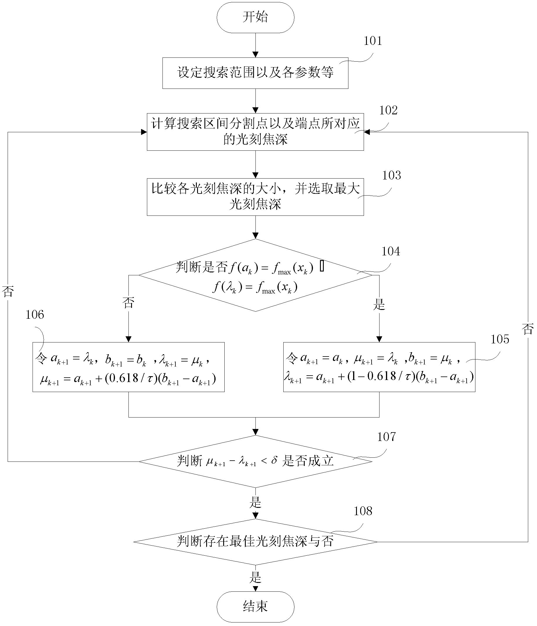
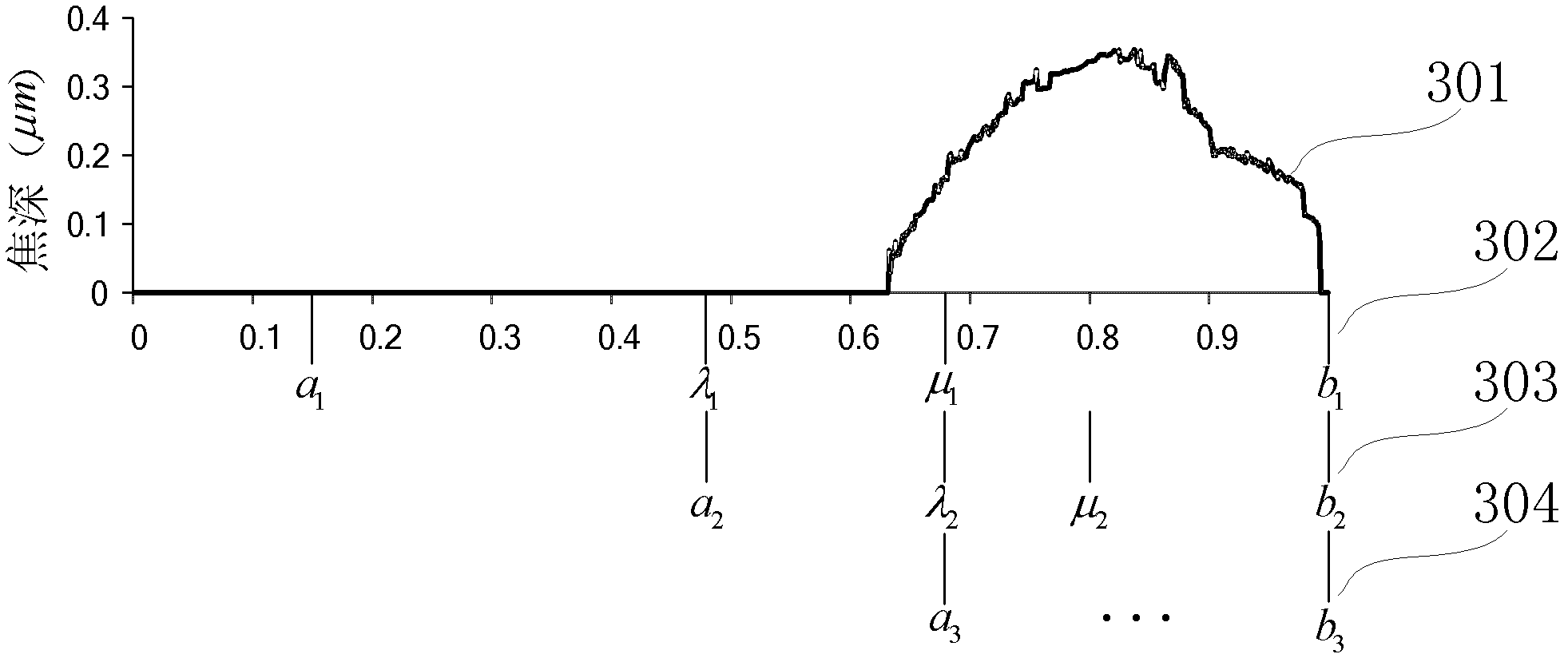
[0035] For example, the value range of the coherence factor is [0.3, 1], and the precision of the coherence factor is 0.001. If the existing ergodic calculation method is used, it is necessary to let the coherence factor take a value every 0.001 from 0.3 to 1 for simulation one by one, so that a total of 701 values ​​need to be taken, that is, 701 calculations are required to obtain the best coherence factor value. If the optimization method of the present invention is sampled, the accuracy of the coherence factor required by us can be achieved and the optimum value of the coherence factor can be obtained only by calculating more than 20 times. Therefore, compared with the prior art, the present invention has a fast calculation speed and can meet the requirement of high-precision calculation.

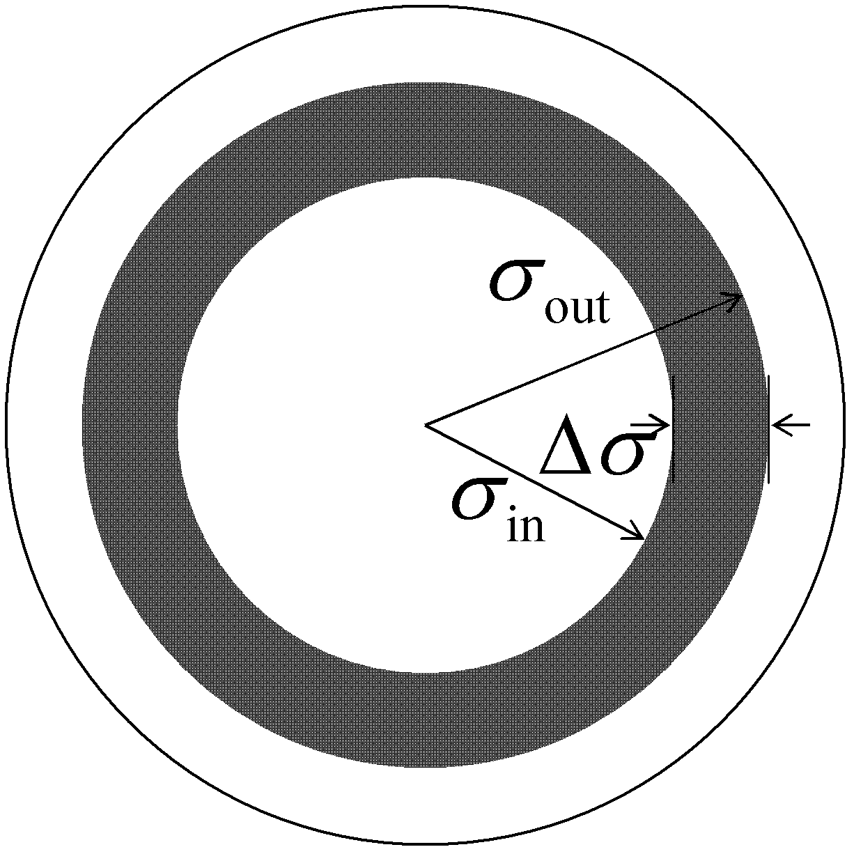
[0036] The optimization process of the present invention will be described below by taking the optimization of the external coherence factor as an example for a lithography machine ill...


PUM


Abstract

The invention provides a method for optimizing the coherent factor of a photoetching machine lighting system. The method specifically comprises the following steps of: determining coherent factor values of an end point and a cutting point in a searching range by using a Hopfinger golden section method, calculating the photoetching focal depths corresponding to the coherent factor values, progressively reducing the searching range according to the calculated photoetching focal depths, and calculating the photoetching focal depths corresponding to a new end point and a cutting point again and sequentially repeating the steps until a predetermined condition and position are met. By the method, the calculation amount is small, and the photoetching focal depths meeting the requirements can be acquired.

Description

technical field [0001] The invention relates to a method for optimizing the coherence factor of an illumination system of a lithography machine, and belongs to the field of collaborative optimization design of parameters of a lithography machine. Background technique [0002] At present, large-scale integrated circuits are generally manufactured by photolithography systems. The lithography system is mainly divided into five parts: light source, illumination system, mask, projection system and wafer. The light emitted by the light source is incident on the mask after being shaped by the lighting system, and the opening of the mask is partially transparent; after passing through the mask, the light is incident on the wafer coated with photoresist through the projection system, so that the mask pattern is copied on the wafer . [0003] Depth of focus in lithography is one of the main parameters for evaluating the performance of a lithography system. It is defined as: within a...

Claims


Application Information

Patent Timeline
IPC IPC(8): G03F7/20
Inventor 李艳秋郭学佳
Owner BEIJING INSTITUTE OF TECHNOLOGYGY
Why Eureka
Try Eureka