
Etching device and circuit board etching method

A technology for etching devices and circuit boards, which is applied in printed circuits, spray devices, and chemical/electrolytic methods to remove conductive materials, etc., can solve the problems of fast flow, etching, and updating, and can prevent the pool effect and improve uniformity. performance, preventing over-corrosion

Inactive Publication Date: 2011-11-23
AVARY HLDG (SHENZHEN) CO LTD +1
View PDF3 Cites 8 Cited by
  • Summary
  • Abstract
  • Description
  • Claims
  • Application Information

AI Technical Summary

Problems solved by technology

However, when the etching device is used to etch the circuit board, since the number of nozzles and the length of each nozzle are consistent, the etchant will flow out of the board from the edge area of ​​the circuit board, so that the update rate of the etchant in the edge area of ​​the circuit board is relatively low. Fast, and accumulate in the central area of ​​the circuit substrate to form a pool, resulting in a pool effect
The pool effect will cause the etchant in the central area of ​​the circuit substrate to update slowly, and the accumulated etchant film will reduce the amount of erosion on the circuit, which is prone to insufficient etching of the circuit, while the etchant in the edge area of ​​the circuit substrate flows fast. The update is faster, and the line over-eclipse is prone to occur
That is, the pool effect will lead to uneven etching of the circuit substrate, especially easily lead to uneven circuit width of the final circuit board, and the conductive circuit connection in the central area
In order to obtain sufficient line width, excess line width has to be reserved for the circuit board edge area, which greatly reduces the line density of the circuit board

Method used


Image

  • Etching device and circuit board etching method
  • Etching device and circuit board etching method
  • Etching device and circuit board etching method

Examples


Embodiment Construction

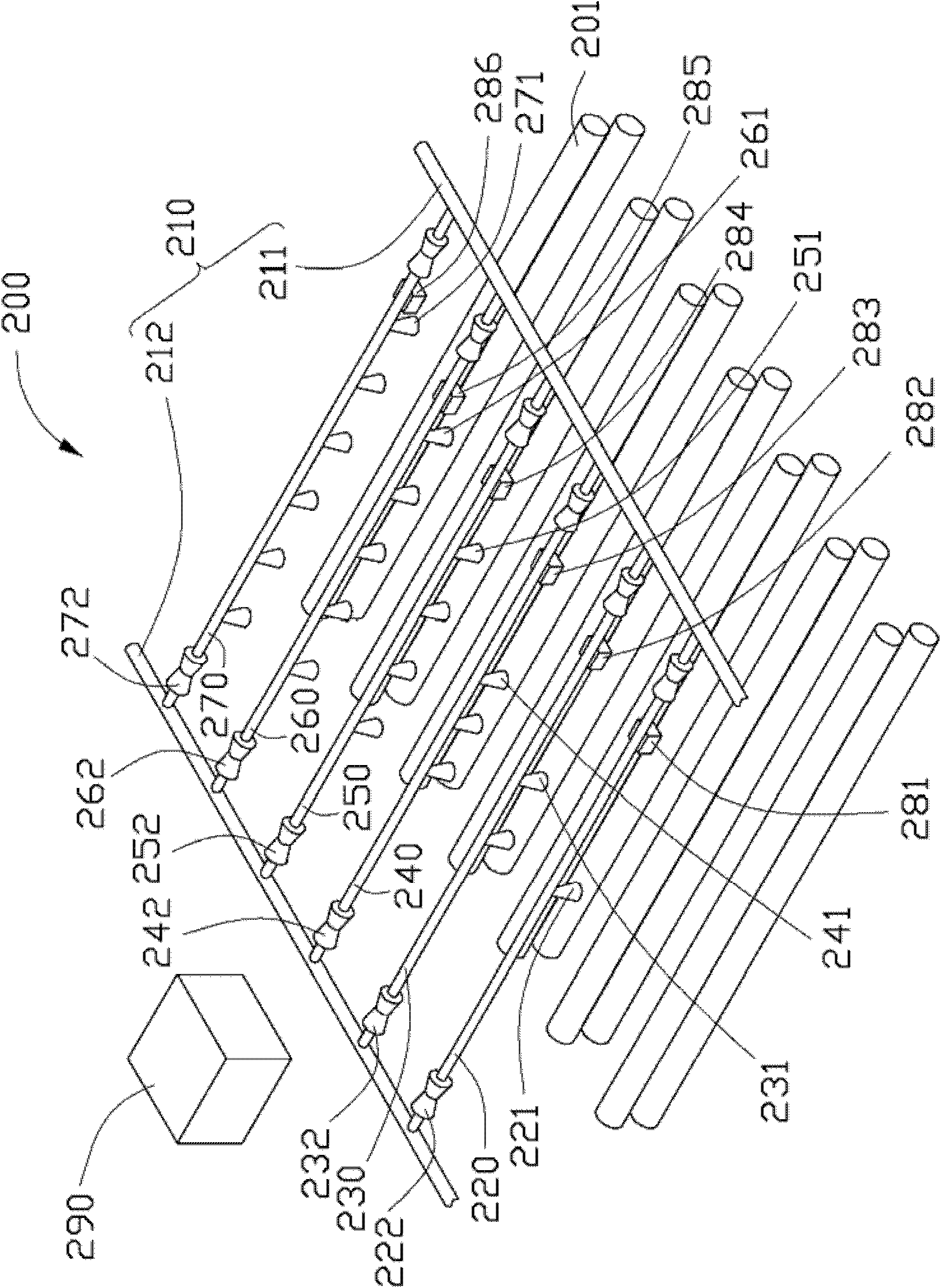
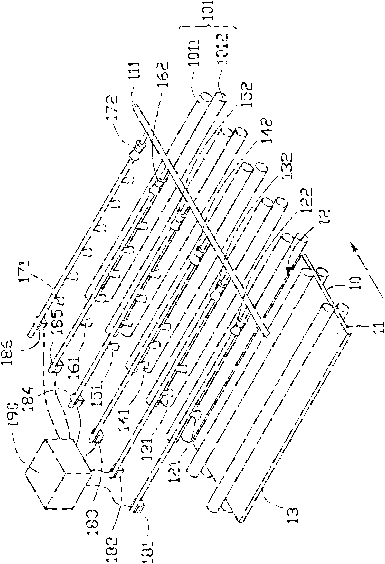
[0057] The etching device and the method for etching a circuit board provided by the technical solution will be described in detail below in conjunction with multiple drawings and multiple embodiments.

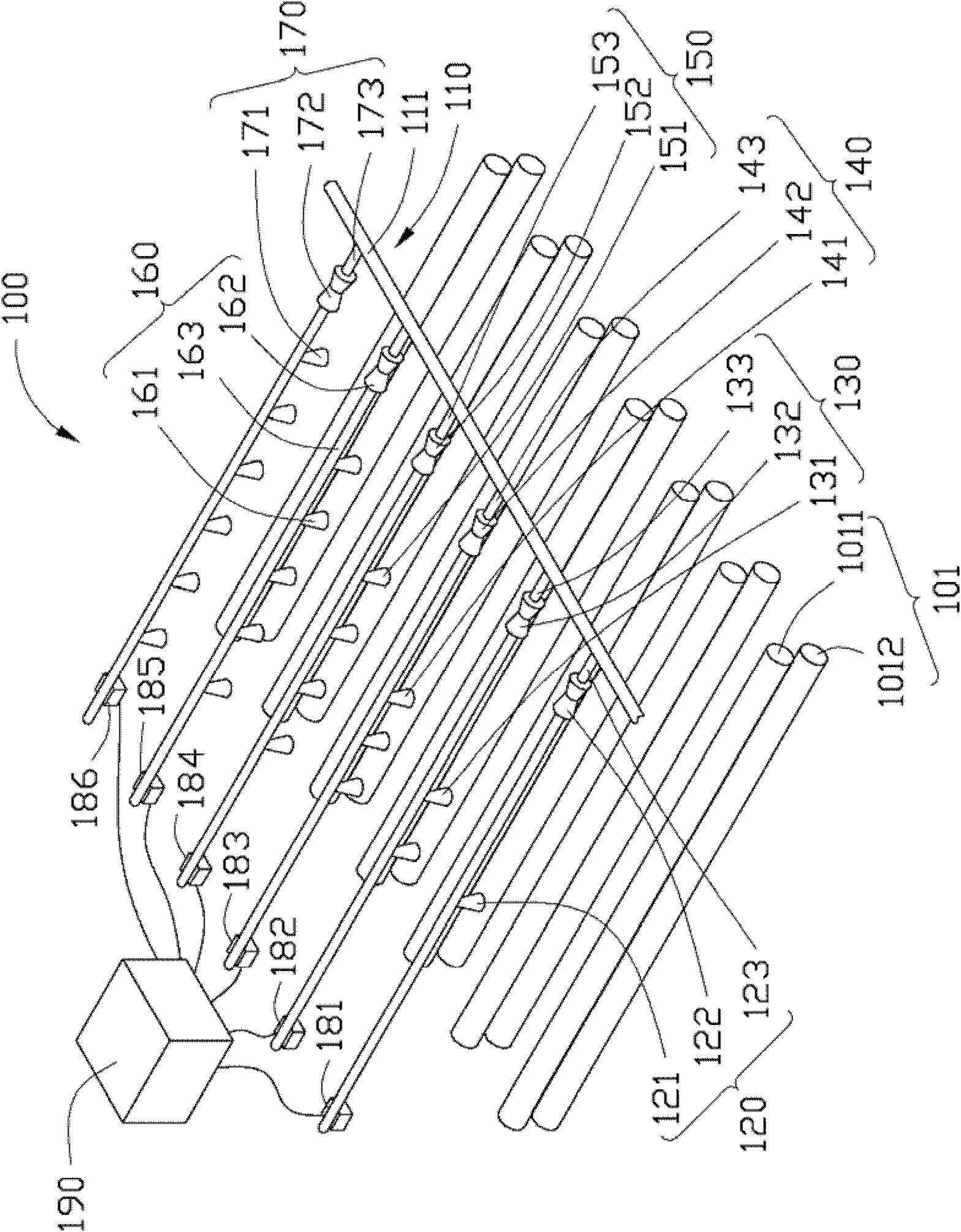
[0058] see figure 1 , the etching device 100 provided by the first embodiment of the technical solution includes an infusion device 110, a first nozzle 120, a second nozzle 130, a third nozzle 140, a fourth nozzle 150, a fifth nozzle 160, a sixth nozzle Nozzle 170, first sensor 181, second sensor 182, third sensor 183, fourth sensor 184, fifth sensor 185, sixth sensor 186, controller 190 and Delivery device 101.

[0059]In this embodiment, the infusion device 110 includes an infusion tube 111 . The infusion pipe 111 is used to supply etching solution to the first nozzle 120 , the second nozzle 130 , the third nozzle 140 , the fourth nozzle 150 , the fifth nozzle 160 and the sixth nozzle 170 . Certainly, a valve may be installed on the infusion tube 111 to control whether th...


PUM

PropertyMeasurementUnit
lengthaaaaaaaaaa
widthaaaaaaaaaa

Abstract

The invention relates to an etching device which comprises a plurality of spray pipes, a plurality of sensors and a controller, wherein the spray pipes are successively arranged in parallel in a direction perpendicular to the transfer direction of a circuit board, each spray pipe comprises spray nozzles and a valve arranged on the spray pipe, the quantity of the spray nozzles on each spray pipe along the transfer direction of the circuit board is successively and gradually increased, the distances between every two adjacent spray nozzles on each spray pipe are equal, the spray nozzles on eachspray pipe are symmetrically distributed in relative to the same straight line perpendicular to the spray pipes, and the valve is used for controlling whether the spray nozzles located on the same spray pipe with the valve spray an etching liquid or not; the sensors are in one-to-one correspondence to the spray pipes and are used for sensing the position relationship between the circuit board andthe spray pipe corresponding to each sensor; and the controller is electrically connected with the sensors and the valves and is used for controlling the opening and closing of the valve corresponding to each sensor according to the sensing results so as to control whether the spray nozzles located on the same spray pipe with the valve spray the etching liquid or not. The invention also relates to a method for etching a circuit board by using the etching device.

Description

technical field [0001] The invention relates to the field of circuit board manufacturing, in particular to an etching device used in a circuit board etching process and a method for etching a circuit board. Background technique [0002] With the rapid development of electronic technology, the integration of circuit boards is getting higher and higher, and the conductive lines of the circuit board are made more and more finely, which requires the dimensional tolerance of the conductive lines of the same circuit board to be as small as possible, that is, the etching process in the etching process The effect needs to be as consistent as possible. [0003] The etching production line has a high degree of automation and low cost, and is widely used in circuit board production. This process uses horizontal rollers to drive the circuit substrate, and uses a linear nozzle type etching device equipped with multiple nozzles to spray etching liquid on the circuit substrate. However, ...

Claims


Application Information

Patent Timeline
Patent Type & Authority Applications(China)
IPC IPC(8): H05K3/06C23F1/02G05B19/04
CPCH05K3/0085H05K2203/1509B05B12/122H05K2203/1545B05B13/0221C23F1/08H05K2203/075
Inventor 蔡宗青郭同尧
Owner AVARY HLDG (SHENZHEN) CO LTD
Learn More