
Etching device using extreme-edge gas pipeline

A technology for etching devices and gas pipelines, which is applied in the manufacture of discharge tubes, electrical components, semiconductors/solid-state devices, etc., and can solve problems such as difficult adjustment of wafer etching environment, differences in etching environments, and reduced yield of semiconductor devices

Inactive Publication Date: 2013-07-24
SEMICON MFG INT (SHANGHAI) CORP
View PDF6 Cites 8 Cited by
  • Summary
  • Abstract
  • Description
  • Claims
  • Application Information

AI Technical Summary

Problems solved by technology

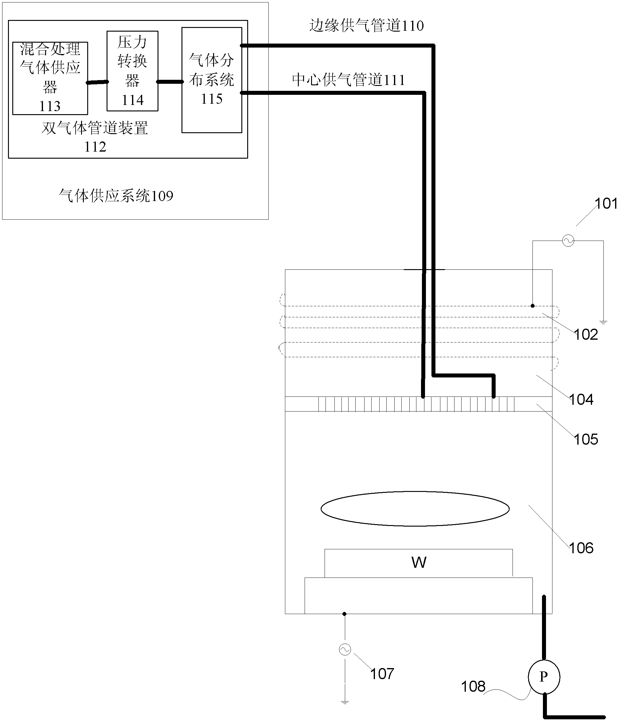
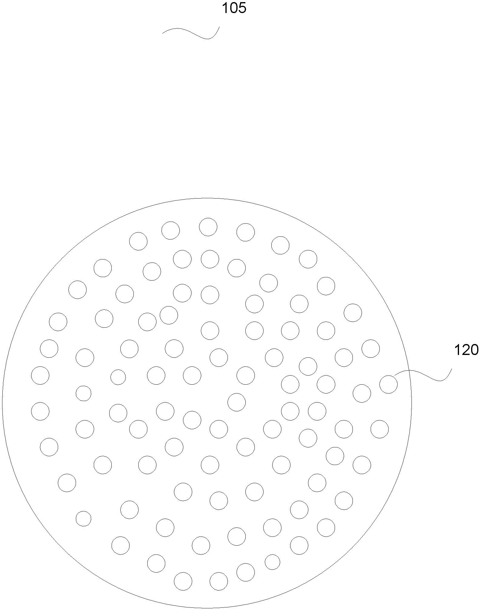
The lower part of the etching device 101 has a suction device vacuum pump 108. Generally, the gas in the edge area of ​​the wafer is drawn away earlier than the gas in the central area, and the bottom view of the traditional gas shower head 105 is as follows: figure 2 As shown, it is generally flat and full of circular gas injection holes 120, which all cause the etching environment at the edge of the wafer to be very different from the center of the wafer, and it is difficult to finely adjust the etching environment at the extreme edge of the wafer.
[0004] Due to the uneven distribution of gas in the center area and the edge area of ​​the wafer during the etching process, there are differences in the etching environment, etc., there is a load effect from the center to the edge, so that the center area of ​​the wafer and the edge of the wafer The etching rate of the area is different, resulting in uneven etching of the wafer surface, resulting in uneven size of through holes or other devices formed between the edge area and the central area of ​​the wafer, especially at the extreme edge of the wafer, reducing the semiconductor device yield
During the processing of 12-inch wafers, the uniformity of the wafer edge has been difficult to control well, and for 18-inch wafers, the uniformity problem is even more serious

Method used


Image

  • Etching device using extreme-edge gas pipeline
  • Etching device using extreme-edge gas pipeline
  • Etching device using extreme-edge gas pipeline

Examples


Embodiment Construction

[0025] In the following description, numerous specific details are given in order to provide a more thorough understanding of the present invention. It will be apparent, however, to one skilled in the art that the present invention may be practiced without one or more of these details. In other examples, some technical features known in the art are not described in order to avoid confusion with the present invention.

[0026] In order to thoroughly understand the present invention, specific embodiments will be proposed in the following description, in order to illustrate how the present invention improves the problems existing in the prior art. Obviously, the practice of the invention is not limited to specific details familiar to those skilled in the semiconductor arts. Preferred embodiments of the present invention are described in detail below, however, the present invention may have other embodiments besides these detailed descriptions.

[0027] An embodiment of the pres...


PUM


Abstract

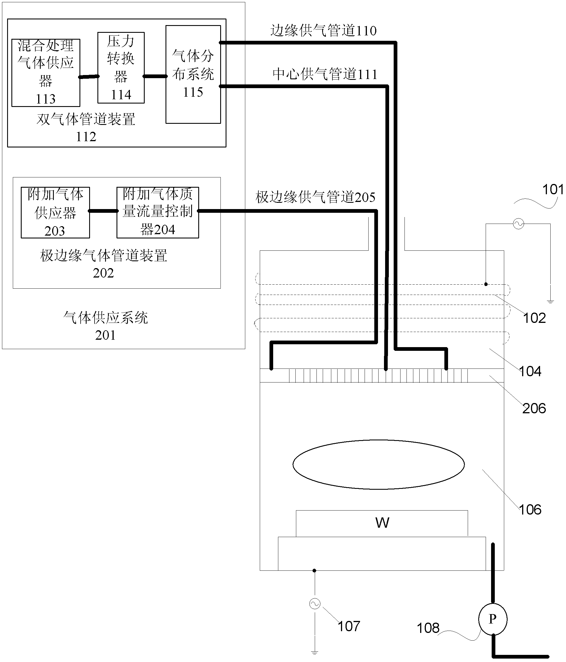
The invention provides an etching device which comprises a gas supply system and an etching reaction chamber. The etching reaction chamber comprises a gas sprayer which is connected with a double-gas pipeline device and an extreme-edge gas pipeline device. The gas supply system comprises the double-gas pipeline device and the extreme-edge gas pipeline device, wherein the double-gas pipeline device is used for supplying gas for the center part and the edge part of an etched wafer, and the extreme-edge gas pipeline device is used for supplying etching reaction gas for the extreme-edge of the etched wafer. In the etching process, through changes of gas ingredients and gas flow amount at the extreme-edge position of the wafer, etching evenness of the surface of the wafer is improved, and meanwhile the etching speed is delicately controlled.

Description

technical field [0001] The invention relates to the field of semiconductor manufacturing, in particular to an etching device using an extreme edge gas pipeline. Background technique [0002] With the wide application of electronic equipment, the manufacturing process of semiconductors has been developed rapidly. The semiconductor manufacturing process involves two basic etching processes: dry etching and wet etching. Among them, dry etching is to expose the wafer to the plasma generated by the etching gas, and the plasma reacts physically and chemically with the wafer, thereby selectively removing unnecessary materials from the wafer surface. At present, dry etching, which can make circuit patterns finer, is more and more widely used. As the process size of integrated circuits develops toward a finer structure, higher technical requirements are put forward for the processing technology. However, when the wafer size that can be processed in the industry develops from 12 in...

Claims


Application Information

Patent Timeline
IPC IPC(8): H01L21/67H01J37/32
Inventor 符雅丽王新鹏
Owner SEMICON MFG INT (SHANGHAI) CORP
Learn More