Current sensor having field screening arrangement including electrical conductors sandwiching magnetic permeability layer

A technology of current sensor and magnetic field sensor, which is applied in the direction of voltage/current isolation, indicating the existence of current/voltage, instruments, etc., and can solve the problems of not providing primary current measurement and not providing linearity, etc.

Inactive Publication Date: 2011-11-23
HONEYWELL INT INC
View PDF6 Cites 10 Cited by
  • Summary
  • Abstract
  • Description
  • Claims
  • Application Information

AI Technical Summary

Problems solved by technology

However, such sensors usually do not provide sufficiently accurate primary current measurements, nor do they usually provide sufficient linearity (between the current to be measured flowing as primary current and the magnetic flux reaching the magnetic sensor)

Method used


Image

  • Current sensor having field screening arrangement including electrical conductors sandwiching magnetic permeability layer
  • Current sensor having field screening arrangement including electrical conductors sandwiching magnetic permeability layer
  • Current sensor having field screening arrangement including electrical conductors sandwiching magnetic permeability layer

Examples


Embodiment Construction

[0023] The present invention is described with reference to the drawings, wherein like reference numerals are used throughout the several figures to indicate similar or equivalent elements. The drawings are not drawn to scale and are provided solely for the purpose of illustrating the invention. Aspects of the invention are described below with reference to exemplary applications for illustration. It should be understood that numerous specific details, relationships, and methods are set forth in order to provide a thorough understanding of the invention. One skilled in the relevant art will readily recognize, however, that the invention may be practiced or otherwise practiced without one or more of the specific details. In other instances, well-known structures or operations have not been shown in detail to avoid obscuring the invention. The invention is not limited by the illustrated ordering of acts or events, as some acts may occur in different orders and / or concurrently ...


PUM


Abstract

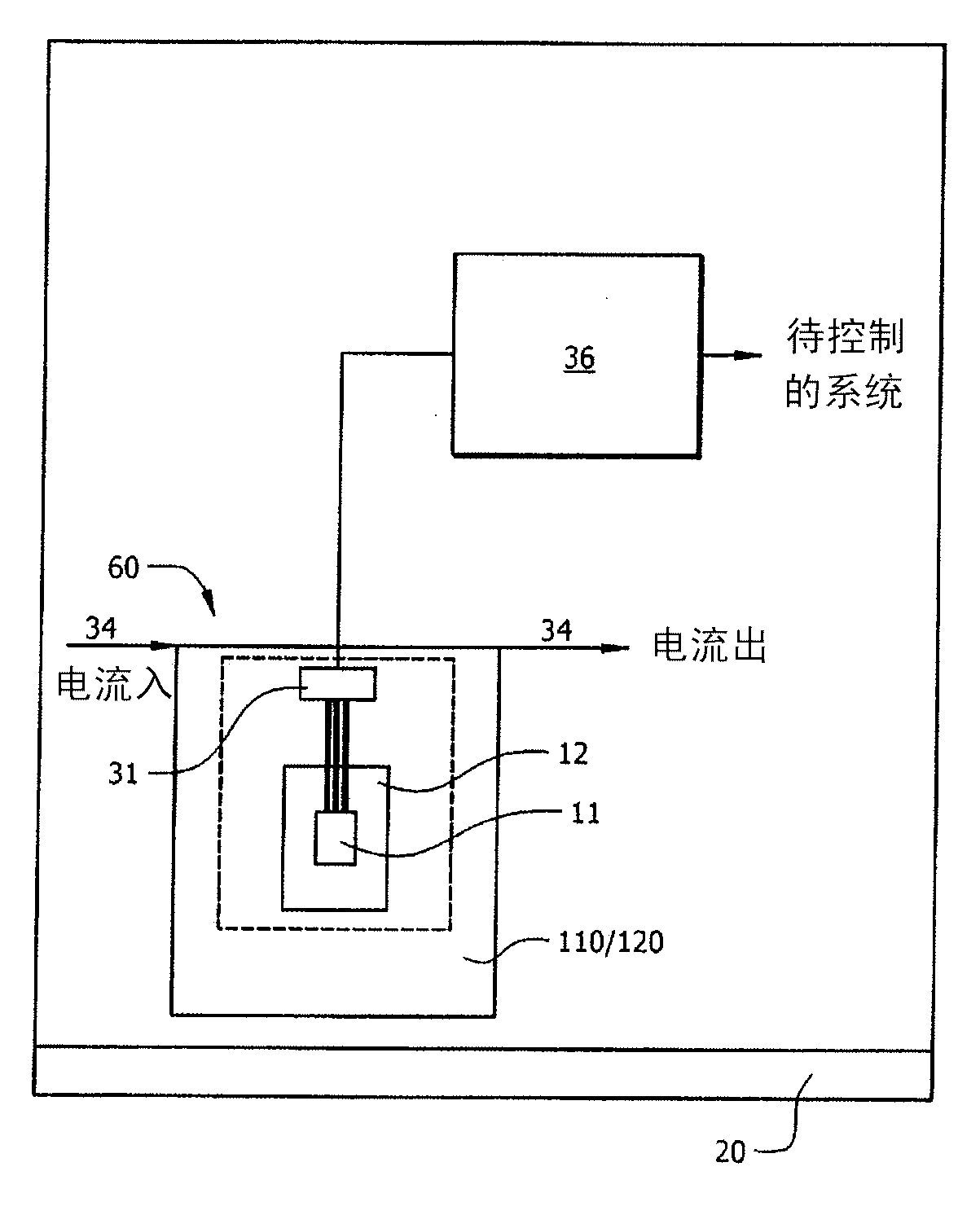
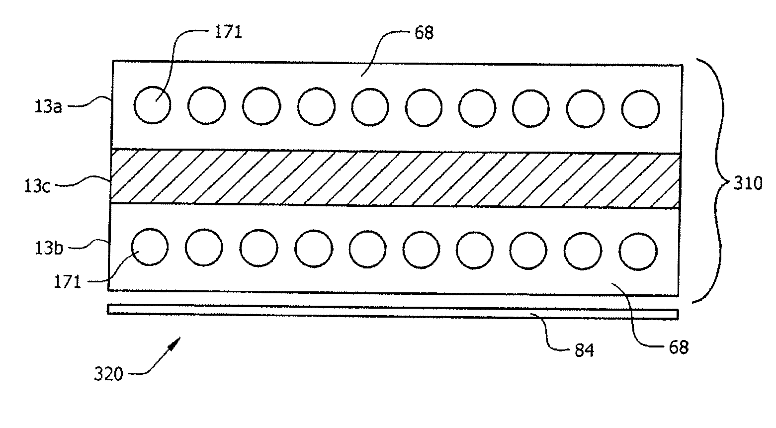
A current sensor includes a magnetic field sensing element, a first conductor including sandwich structure and second conductor including sandwich structure electrically coupled to one another. The magnetic field sensing element is interposed between the first and second sandwich structure. The magnetic field sensing element is operable to receive magnetic flux lines resulting from current flowing through the first and second conductor sandwich structure. The first and second conductor sandwich structure each include a top portion including at least a first electrical conductor, a bottom portion including at least a second electrical conductor, and a layer of magnetic permeable material different from the first and second electrical conductor interposed between the top portion and bottom portion.; The magnetic permeable material shields (bypasses) stray magnetic fields from reaching the magnetic field sensing element, but does not measurably influence the magnetic field generated by the primary current to be measured.

Description

technical field [0001] The present invention generally relates to current sensors based on magnetic field sensing. Background technique [0002] Conventional magnetic field-based current sensors typically include a magnetic field sensor, an iron core, and an amplifier. An iron core surrounds an electrical conductor, usually comprising copper, to carry the current to be measured, which causes a magnetic field to be generated in the iron core. Magnetic field sensors are arranged in gaps in the core. Thus, the field lines of the magnetic field induced in the core by the current to be measured pass through the magnetic field sensor. Magnetic field sensors generate an electrical output signal substantially proportional to the current to be measured, and this signal is amplified by an amplifier such as an operational amplifier. [0003] The iron core in a conventional current sensor primarily serves two functions. First, the magnetic field induced by the current to be measured...

Claims


Application Information

Patent Timeline
Patent Type & Authority Applications(China)
IPC IPC(8): G01R15/20G01R19/15
CPCG01R33/091G01R33/07G01R15/207
Inventor H.金策尔
Owner HONEYWELL INT INC
Why Eureka
Try Eureka