Components for led light bulbs and manufacturing method thereof

A technology of LED light bulbs and manufacturing methods, which is applied to components of lighting devices, semiconductor devices of light-emitting elements, and damage prevention measures for lighting devices, which can solve the problems of reduced light output power and short life, and achieve improved joint adhesion Sexuality, the effect of reducing the cost of raw materials

Inactive Publication Date: 2011-11-30
SUMITOMO LIGHT METAL INDS LTD +1
View PDF14 Cites 3 Cited by
  • Summary
  • Abstract
  • Description
  • Claims
  • Application Information

AI Technical Summary

Problems solved by technology

[0004] On the other hand, the light output power of LED elements generally decreases as the temperature rises. In addition, when the ambient temperature is high compared with the case where the ambient temperature is low, the light output power decreases more with the passage of time, and the life is short.

Method used


Image

  • Components for led light bulbs and manufacturing method thereof
  • Components for led light bulbs and manufacturing method thereof
  • Components for led light bulbs and manufacturing method thereof

Examples


Embodiment 1

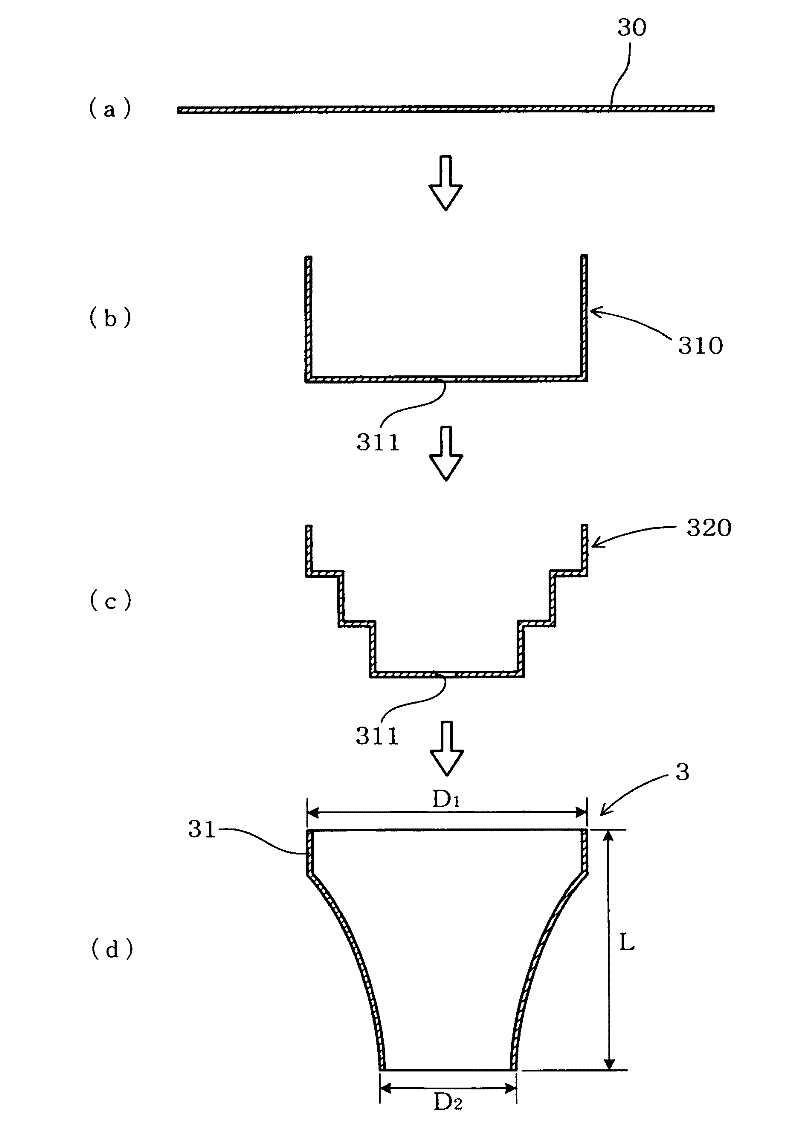
[0083] use Figure 1 to Figure 6 , the components for LED light bulbs and the manufacturing methods thereof according to the embodiments of the present invention will be described.

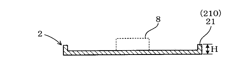
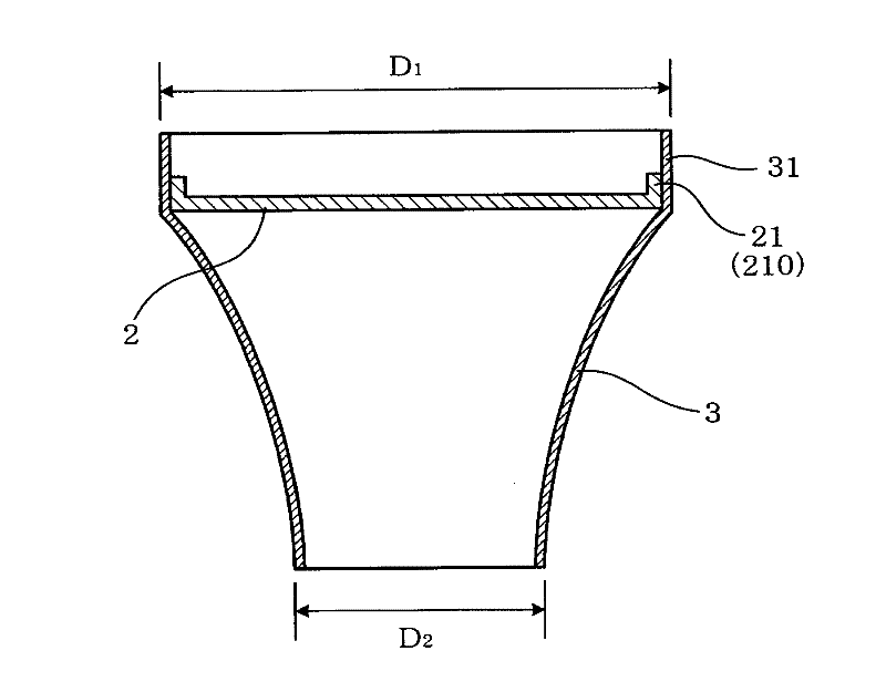
[0084] Parts 1 for the LED light bulb in this example are as follows: Figure 6 As shown, there is a disc-shaped LED mounting substrate 2 made of an aluminum alloy plate on which an LED element 8 is mounted, and a heat dissipation member 3 formed into a substantially conical shape by applying plastic working to the aluminum alloy plate. like Figure 5 As shown, the outer peripheral edge portion 21 of the LED mounting substrate 2 and the opening end portion 31 of the heat dissipation member are bonded by hemming.

[0085] Hereinafter, further details will be given.

[0086]

[0087] As the heat radiating member 3, an unpainted aluminum alloy plate not coated with a synthetic resin film was used as a material. Specifically, A8021-O in material quality and a size of 0.5 mm in thickness×100 mm in ...

Embodiment 2

[0102] This example is based on the structure of Example 1, and differs only in the use of a precoated aluminum alloy plate coated with a synthetic resin film on the material of the heat sink member 3 . Precoated aluminum alloy panels were produced in the following manner.

[0103]

[0104] like Figure 7 As shown, a pre-coated aluminum alloy plate 300 for the heat dissipation component 3 is fabricated.

[0105] As the aluminum alloy plate 30 , an aluminum alloy plate having a material quality of A8021-O and a size of 0.5 mm thickness×100 mm width×100 mm length was prepared.

[0106] Next, after degreasing both surfaces of the aluminum alloy plate 30 with an alkaline degreasing agent, the aluminum alloy plate 30 was immersed in a phosphoric acid chromate solution to perform a chemical generation treatment. The obtained chemically formed film (phosphoric acid chromate film) 302, as the Cr content in the film, is 20 ± 5 mg / m 2 In the range.

[0107] Next, a synthetic resin...

Embodiment 3

[0111] This example Figure 8 ~ Figure 10 Shown is an example based on the structure of Embodiment 1, adopting the following method: changing the form of the hemming process of the outer peripheral edge portion 21 of the LED mounting substrate 2 and the opening end portion 31 of the heat dissipation member 3, and Orientation performs hemming at six locations only.

[0112] like Figure 8 , Figure 9 As shown, in the heat radiating member 3 used in this example, after forming the radiating member 3 in the same manner as in Example 1, the opening end 31 is notched at six places in the circumferential direction, and six remaining convex shapes are provided. The opening end tab portion 315 of the first position. On the other hand, the board|substrate 2 for LED mounting is made into the shape which has the flange part 210 in the whole circumference similar to Example 1. As shown in FIG. Furthermore, the hemming process is performed only on the opening-end protrusion part 315 of...


PUM


Abstract

The invention provides a part used for an LED bulb, which is excellent in heat radiation performance and productivity, simple in structure and low in cost. The part comprises a disc-shaped substrate used for carrying LED components and composed of aluminum alloy plates (2) and a roughly cylindrical or cone-shaped heat radiation component (3) prepared by applying plasticity to an aluminum alloy plate. An outer peripheral portion (21) of the substrate (2) and an opening end portion (31) of the heat radiation component are engaged via flanging manufacturing. Preferably, the outer peripheral portion (21) of the substrate (2) are provided with roughly right-angle-shaped flanges (210), flanging manufacturing is conducted on the opening end portion (31) of the heat radiation component towards the inside direction, the heat radiation component (3) is shaped by using a precoated aluminum alloy plate, and the precoated aluminum alloy plate is prepared by precoating a heat radiating film containing heat radiation substances on two sides or one side of an aluminum alloy plate.

Description

technical field [0001] The present invention relates to a component in an LED light bulb with a built-in LED (light emitting diode) element. Background technique [0002] With the increase in performance of LEDs, studies have been made on the use of lamps (LED lamps) using LEDs as light sources as next-generation lighting devices. Various types of LED lights are conceivable, but light bulb-type LED lights (hereinafter referred to as LED light bulbs) that can be replaced with incandescent light bulbs widely used in general households are particularly attracting attention. [0003] Compared with conventional incandescent light bulbs, LED light bulbs can be said to be in line with energy-saving requirements based on the current thinking of preventing global warming because they consume about 1 / 8 of the power consumption and have a life span of about 40 times. Excellent item. [0004] On the other hand, the light output power of LED elements generally decreases as the temperat...

Claims


Application Information

Patent Timeline
IPC IPC(8): F21S2/00F21V17/10F21V29/00F21Y101/02F21V29/503F21V29/85
CPCF21K9/60F21V15/01F21V29/00F21V29/89F21Y2101/00F21Y2103/37
Inventor 城户孝聪水野肇
Owner SUMITOMO LIGHT METAL INDS LTD
Why Eureka
Try Eureka