Lampshades and lamps using the same
A technology for lampshades and lamps, applied in the field of lampshades and lamps, can solve the problems of reducing light output efficiency and increasing light loss, and achieve the effects of improving light output efficiency, reducing light loss, and reducing the probability of total reflection
- Summary
- Abstract
- Description
- Claims
- Application Information
AI Technical Summary
Problems solved by technology
Method used
Image

Examples
Embodiment Construction
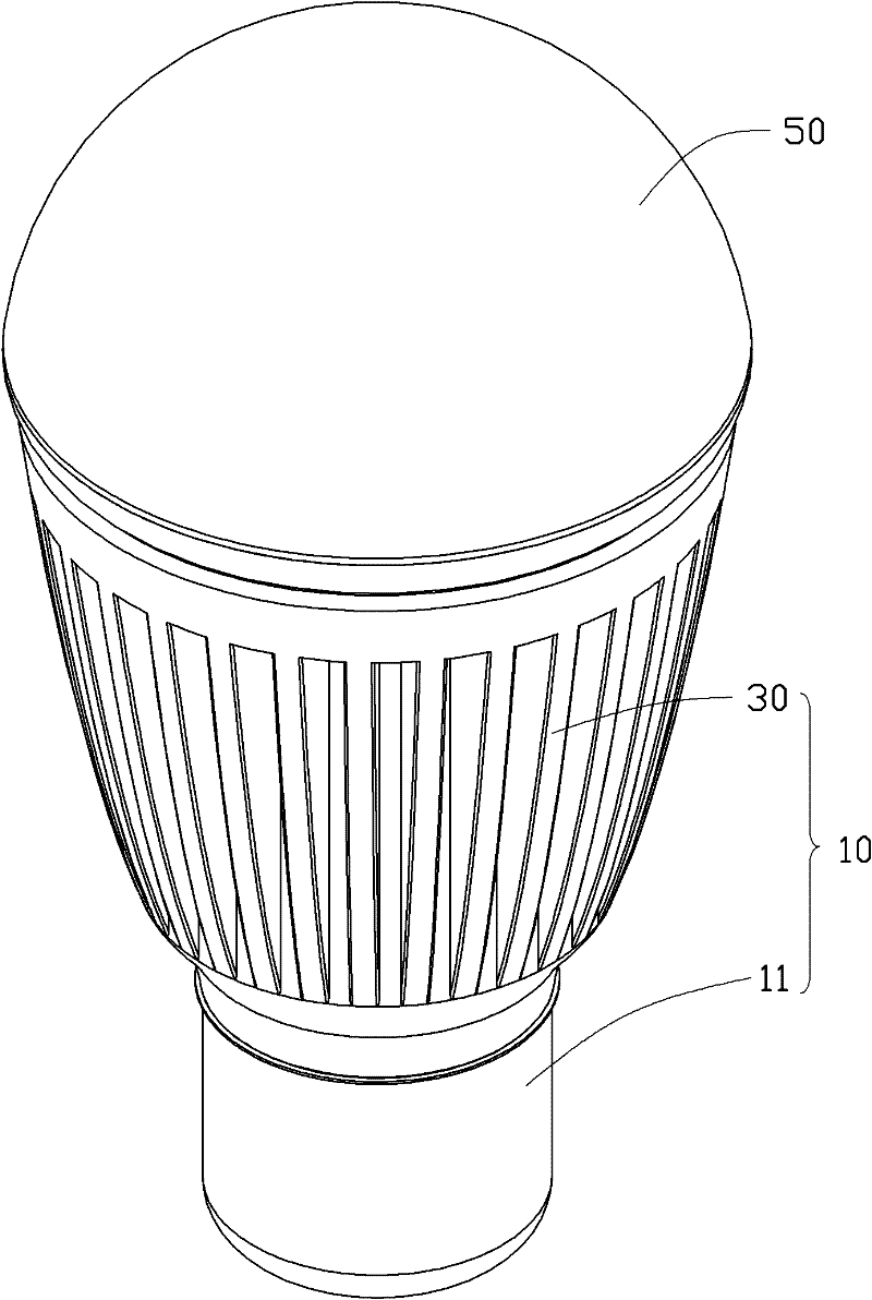
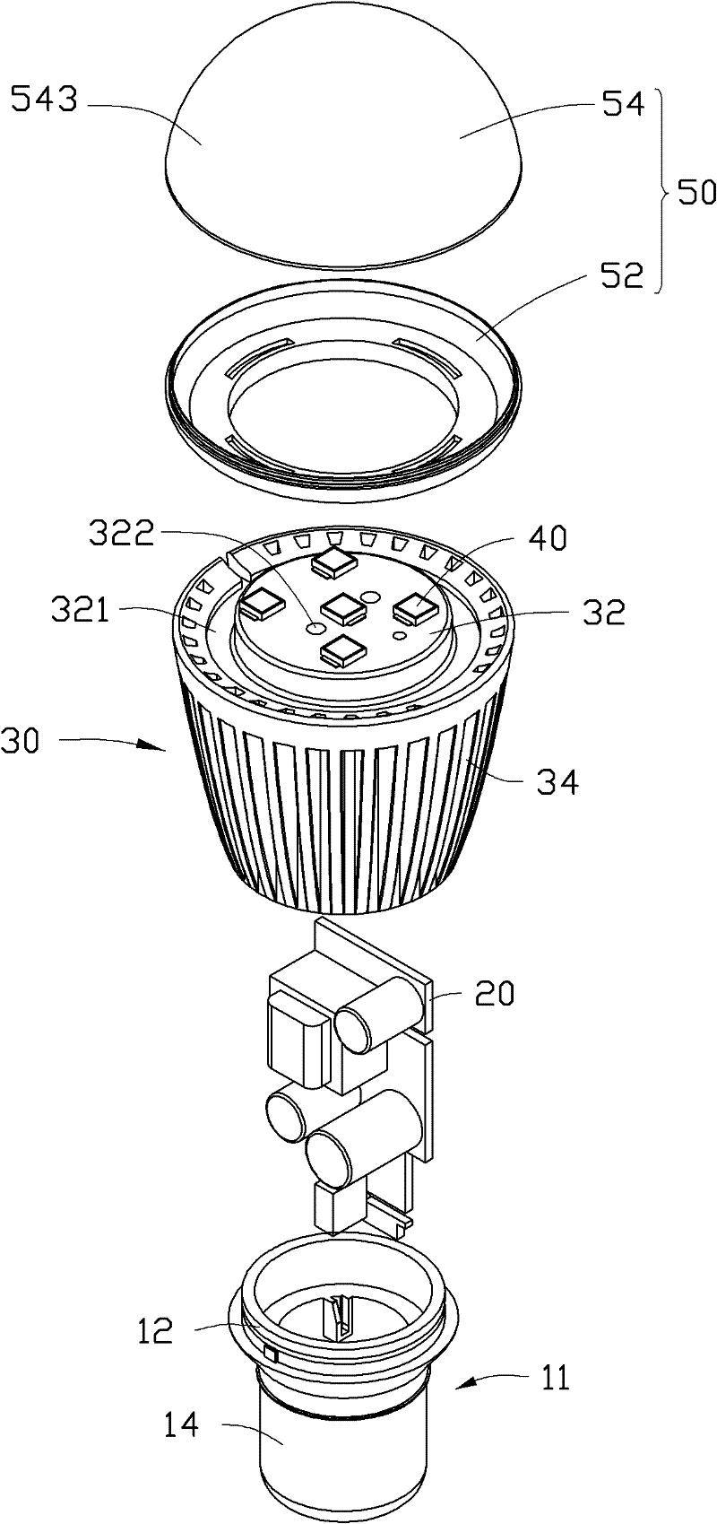
[0035] see Figure 1 to Figure 3 , A lamp provided by an embodiment of the present invention includes a lamp holder 10 , a power supply module 20 , a heat sink 30 , an LED module 40 and a lampshade 50 .
[0036] The lamp holder 10 includes a receiving portion 11 at the bottom of the lamp holder 10 and a heat sink 30 at the top of the lamp holder 10 . The receiving portion 11 includes an insulating portion 12 and an electrical connector 14 . The electrical connector 14 is sheathed on the lower end of the insulating part 12 for electrical connection with an external power source to provide the electrical energy required for the lamp to work. The insulating part 12 is fixedly connected with the radiator 30 .
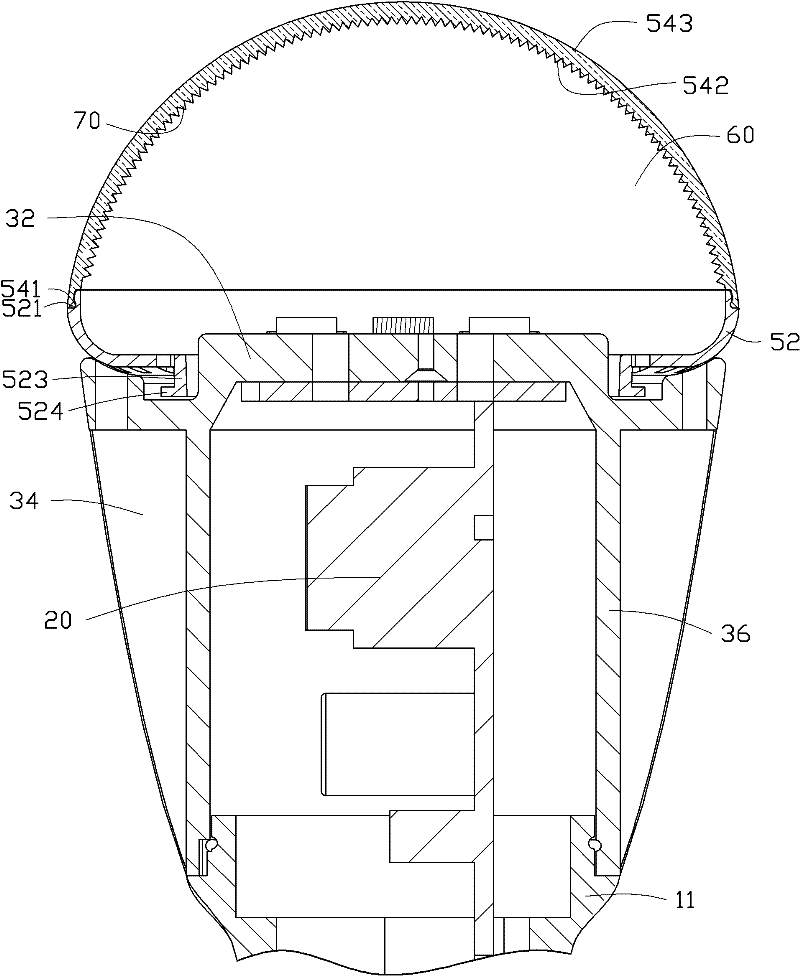
[0037] The power supply module 20 is disposed in the heat sink 30 , and is electrically connected with the electrical connector 14 on the receiving portion 11 and the LED module 40 to provide a driving voltage for the LED module 40 .
[0038] The heat sink 30 includes a ...
PUM
 Abstract
Description
Claims
Application Information
 - Generate Ideas
- Intellectual Property
- Life Sciences
- Materials
- Tech Scout
- Unparalleled Data Quality
- Higher Quality Content
- 60% Fewer Hallucinations
Browse by: Latest US Patents, China's latest patents, Technical Efficacy Thesaurus, Application Domain, Technology Topic, Popular Technical Reports.
© 2025 PatSnap. All rights reserved.Legal|Privacy policy|Modern Slavery Act Transparency Statement|Sitemap|About US| Contact US: help@patsnap.com