Detection device and detection method for dynamic process of material micro-domain structure change

A technology of structural change and process detection, which is applied in the field of optical detection, can solve the problems that the focal length of the lens cannot be too short, the numerical aperture objective lens cannot be used, and the large space, etc., and achieve the effect of high repeatability, less human error, and accurate detection position

Inactive Publication Date: 2011-11-30
SHANGHAI INST OF OPTICS & FINE MECHANICS CHINESE ACAD OF SCI
View PDF4 Cites 9 Cited by
  • Summary
  • Abstract
  • Description
  • Claims
  • Application Information

AI Technical Summary

Problems solved by technology

However, this method is not conducive to using the CCD to observe the positions of the two lasers. In order to enable the second laser to detect structural changes, the range of action of the first laser needs to be large, which often causes the sample surface to deviate from the focus of the first laser. position, which requires increasing the laser power; moreover, before the first laser beam acts on the surface of the material, it needs to pass through a lens with a focusing effect. Objective lens with high numerical aperture, which needs to further increase the laser power, and requires a larger space

Method used


Image

  • Detection device and detection method for dynamic process of material micro-domain structure change
  • Detection device and detection method for dynamic process of material micro-domain structure change
  • Detection device and detection method for dynamic process of material micro-domain structure change

Examples


Embodiment Construction

[0042] The present invention will be further described below in conjunction with the embodiments and accompanying drawings.

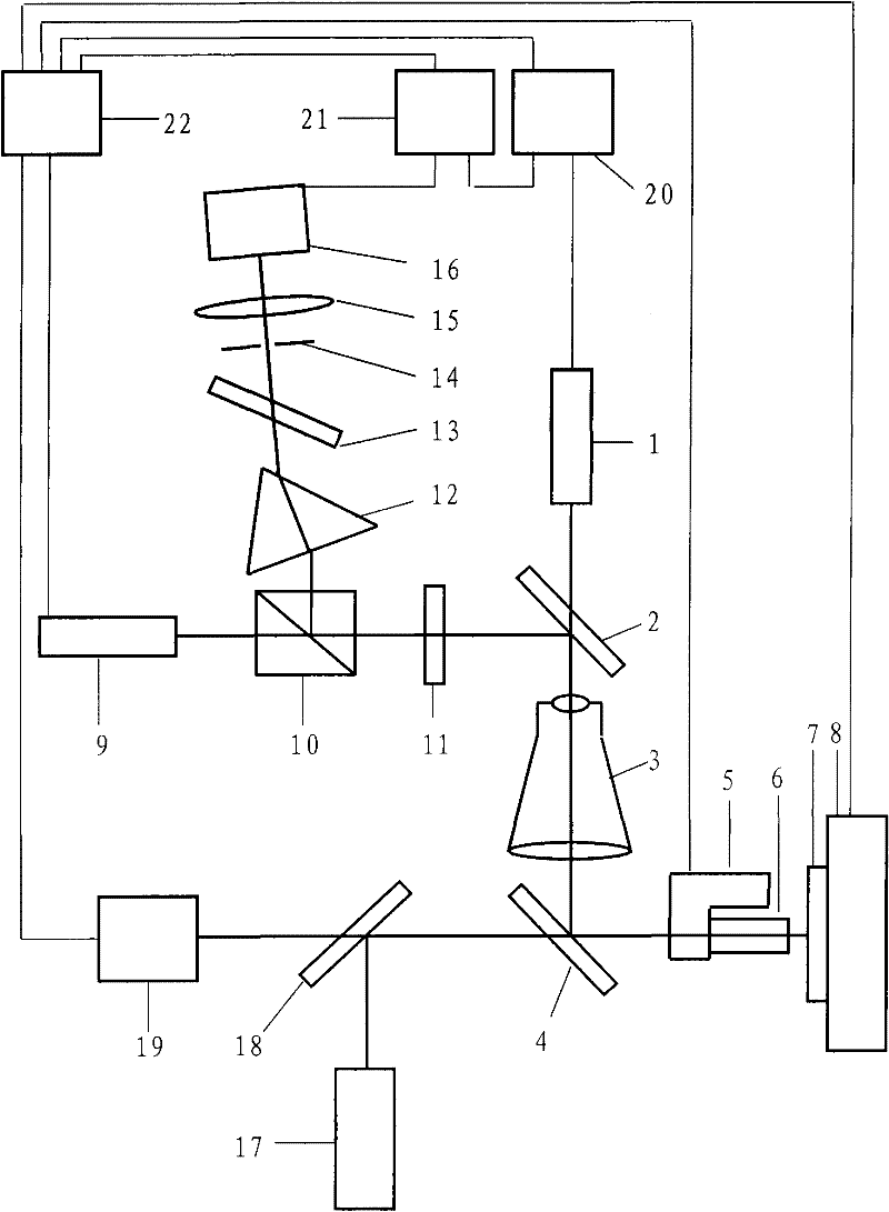
[0043] figure 1 It is an optical path structure diagram of an embodiment of the detection device for the dynamic process of material micro-region structure change realized by the present invention. Such as figure 1 As shown, the detection device for the dynamic process of the material micro-domain structure change includes three parts: the first part is the part where the laser-induced material micro-domain changes, the second part is the part that detects the dynamic process of the material micro-domain structure change, and the third part It is the CCD observation part.

[0044] The part where the laser-induced material micro-domain changes: on its main optical axis, the output laser wavelength λ is sequentially included 1 The first laser device 1, the first spectral beam splitter 2, the beam expander 3, and the second spectral beam splitter 4, aft...


PUM

PropertyMeasurementUnit
transmittivityaaaaaaaaaa
reflectanceaaaaaaaaaa
transmittivityaaaaaaaaaa

Abstract

The invention discloses a detection device and a detection method for dynamics process of structure change of a micro region of a material. The device comprises two paths of laser light, one path of laser light reacts with the material, which results in that the structure of the micro region of the material changes, and the second path of laser light detects the dynamics process of the structure change. In the device and the method, a sample is automatically adjusted to a focal point of the first path of laser light by a CCD (charge coupled device) imaging method and a piezoelectric ceramic, and an objective lens with high numerical aperture is used so as to obtain the structure change of the micro region; the two paths of laser light are coaxial and vertically incident on the surface of the sample, light spots formed on the surface of the sample by the two paths of laser light are simultaneously observed through a CCD, and consequently, and the light spots of the two paths of laser light can be accurately superposed, which facilitates the detection on the dynamics process of the structure change of smaller regions; the utilization rate of the laser light is improved through a polarization beam splitting prism and a quarter wavelength plate, the two coaxial paths of laser light are completely separated by a dispersing prism and a total reflection principle, influence of non-detection light is removed, and detection precision is improved.

Description

technical field [0001] The invention relates to the field of optical detection, in particular to a detection device and a detection method for the dynamic process of material micro-region structure change. Background technique [0002] With the development of laser technology, laser-induced material structure changes are more and more widely used, such as integrated circuits, solar cells, optical devices, etc., and the dynamic process of material structure changes has also been studied more and more. In the process of material structure change, dynamic process and thermodynamic process complement each other. Thermodynamic process refers to the condition that the outside world gives the material a structural change. Kinetic process refers to the dynamic process of material structure change. The study of this process is not only beneficial to A deeper understanding of the properties of materials, such as the transformation of crystalline and amorphous materials, can also be us...

Claims


Application Information

Patent Timeline
Patent Type & Authority Applications(China)
IPC IPC(8): G01N21/84
Inventor 马晓晴魏劲松
Owner SHANGHAI INST OF OPTICS & FINE MECHANICS CHINESE ACAD OF SCI
Why Eureka
Try Eureka