Liquid crystal display device and manufacturing method thereof

A technology of a liquid crystal display device and a manufacturing method, which is applied to static indicators, optics, instruments, etc., and can solve problems such as thickness occupied by conductive adhesive tape, narrow frame design troubles, and light leakage of the plane conversion liquid crystal display device 300, so as to facilitate thinning , reduced design, reduced width effect

Active Publication Date: 2014-03-05
CENTURY DISPLAY (SHENZHEN) CO LTD
View PDF4 Cites 0 Cited by
  • Summary
  • Abstract
  • Description
  • Claims
  • Application Information

AI Technical Summary

Problems solved by technology

Furthermore, in order to ensure the electrical connection between the conductive adhesive plaster 370 and the electromagnetic shielding layer 360, it must be ensured that the conductive adhesive plaster 370 and the electromagnetic shielding layer 360 have a sufficiently long contact area, that is, the conductive adhesive plaster 370 must be in contact with the electromagnetic shielding layer on the color filter substrate 320. The layer 360 has a certain overlapping length in order to achieve good electrical conductivity. The overlapping length b of the conductive adhesive tape 370 and the color filter substrate 320 is generally greater than 0.5 mm (millimeters) in the conventional art. troubled
[0015] Figure 4 Yes figure 2 For the partial enlarged plan view of the 300Q block of the liquid crystal display device, please refer to Figure 4 , an iron frame 350 needs to be set on the conductive adhesive plaster 370. Since the conductive adhesive plaster 370 has a certain thickness, there will be gaps 380 on both sides of the conductive adhesive plaster. problem, which in turn causes poor display of the in-plane switching liquid crystal display device 300
[0016] In addition, the conductive adhesive tape 370 will occupy a certain thickness, therefore, it also causes difficulties for the thinning of the plane switching liquid crystal display device 300.

Method used


Image

  • Liquid crystal display device and manufacturing method thereof
  • Liquid crystal display device and manufacturing method thereof
  • Liquid crystal display device and manufacturing method thereof

Examples


no. 1 example

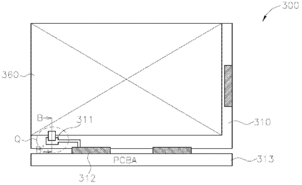
[0048] Figure 5 It is a top view of the plane switching liquid crystal display device according to the first embodiment of the present invention, Image 6 is a perspective view of the plane switching liquid crystal display device of the first embodiment of the present invention, first, as Figure 5 and Image 6 As shown, the plane switching liquid crystal display device 400 includes a first substrate 410, a second substrate 420, a conductive metal layer 411, an electromagnetic shielding layer 460, a flexible printed circuit substrate 412 and a printed circuit board assembly 413, wherein the The second substrate 420 is arranged on the first substrate 410 and the two are oppositely arranged, and a conductive metal layer 411 is arranged on the first substrate 410, and the conductive metal layer 411 of the second substrate 420 and the first substrate 410 Covered with an electromagnetic shielding layer 460, and the electromagnetic shielding layer 460 is electrically connected to...

no. 2 example

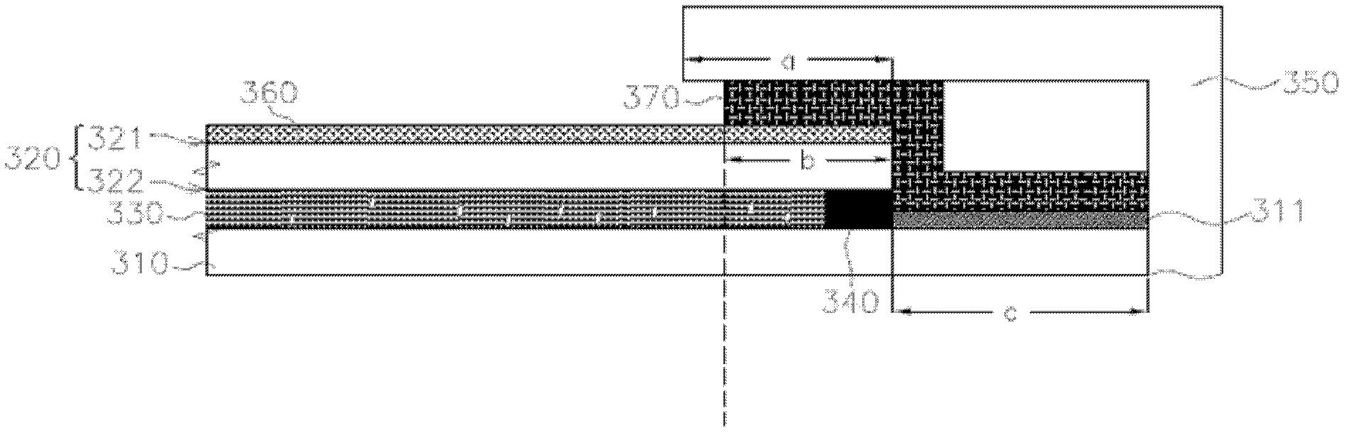
[0064] Figure 10 It is a top view of the plane switching liquid crystal display device according to the second embodiment of the present invention, Figure 11 It is a perspective view of a plane switching liquid crystal display device according to the second embodiment of the present invention, Figure 12 yes Figure 10 A schematic cross-sectional view of a plane-switching liquid crystal display device along line DD'. The plane-switching liquid crystal display device of this embodiment is similar to the plane-switching liquid crystal display device of the first embodiment. Therefore, the same component symbols represent the same components. The difference between this embodiment and the first embodiment is the design of the second substrate and the electromagnetic shielding layer.

[0065] Please merge reference Figure 10 , Figure 11 and Figure 12 , the second substrate 520 includes an upper surface 521 and a lower surface 522, wherein the upper surface 521 is the sur...

no. 3 example

[0077] Figure 14 It is a top view of the plane switching liquid crystal display device of the third embodiment of the present invention, Figure 15 It is a perspective view of a plane switching liquid crystal display device according to the third embodiment of the present invention, Figure 16 yes Figure 14 A schematic cross-sectional view of a plane-switching liquid crystal display device along line EE'. The plane-switching liquid crystal display device of this embodiment is similar to the plane-switching liquid crystal display device of the first embodiment, and the same component symbols represent the same components. The difference between this embodiment and the first embodiment lies in the design of the electromagnetic shielding layer and the addition of an auxiliary part.

[0078] Please refer to Figure 14 , Figure 15 and Figure 16 , in this embodiment, the plane switching liquid crystal display device 600 further includes an auxiliary part 690, the auxiliary ...


PUM

PropertyMeasurementUnit
thicknessaaaaaaaaaa
thicknessaaaaaaaaaa

Abstract

The invention provides a liquid crystal display device for the touch panel. The liquid crystal display device comprises a first substrate, a second substrate, a liquid crystal layer, a plastic frame and an electromagnetic shielding layer, wherein the first substrate and the second substrate are oppositely arranged in a spaced way; the liquid crystal layer is mounted between the first and second substrates; the plastic frame is arranged between the first and the second substrates so as to seal the liquid crystal layer; the electromagnetic shielding layer is arranged on the first and second substrates. And a conductive metal layer arranged in a grounded way is mounted on the first substrate; the conductive metal layer is electrically connected to the electromagnetic shielding layer; the electromagnetic shielding layer comprises a main body part and an extending part. The main body part is arranged on the second substrate; the extending part extends from the main body part to the conductive metal layer of the first substrate so as to electrically connect the main body part with the conductive metal layer.

Description

【Technical field】 [0001] The present invention relates to a liquid crystal display device for a touch panel, in particular to a liquid crystal display device for a touch panel with an electromagnetic shielding layer. 【Background technique】 [0002] Touch display devices have a wide range of applications and have been widely used in monitors of portable notebook computers, input functions of portable personal mobile phones, various information appliances, public information system equipment, and office automation equipment. Wait. [0003] Such as figure 1 As shown, the touch display device is a device formed by laminating a transparent touch panel 100 and a liquid crystal display device 200 . The touch panel 100 is located on the liquid crystal display panel 200 for sensing external touch signals. The liquid crystal display device 200 is used for displaying images. Through the cooperation of the liquid crystal display device 200 and the touch panel 100, users can perform in...

Claims


Application Information

Patent Timeline
Patent Type & Authority Patents(China)
IPC IPC(8): G02F1/133G02F1/1339G02F1/1333G06F3/044
Inventor 李得俊曾迎祥
Owner CENTURY DISPLAY (SHENZHEN) CO LTD
Why Eureka
Try Eureka