peep valve and anesthesia machine with the peep valve

An anesthesia machine and valve core technology, applied in the field of anesthesia machines, can solve the problems of complicated processing of PEEP valve, non-adjustable valve port and valve core, etc., and achieve the effect of simple structure and simple installation.

Active Publication Date: 2011-12-07
BEIJING AEONMED
View PDF5 Cites 4 Cited by
  • Summary
  • Abstract
  • Description
  • Claims
  • Application Information

AI Technical Summary

Problems solved by technology

[0005] The purpose of the present invention is to provide an improved PEEP valve to overcome the defects of complicated processing and non-adjustable between the valve port and the valve core of the existing PEEP valve.

Method used


Image

  • peep valve and anesthesia machine with the peep valve
  • peep valve and anesthesia machine with the peep valve
  • peep valve and anesthesia machine with the peep valve

Examples


Embodiment Construction

[0019] It should be noted that, in the case of no conflict, the embodiments in the present application and the features in the embodiments can be combined with each other. The present invention will be described in detail below with reference to the accompanying drawings and examples.

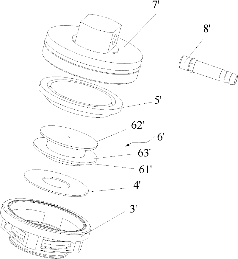
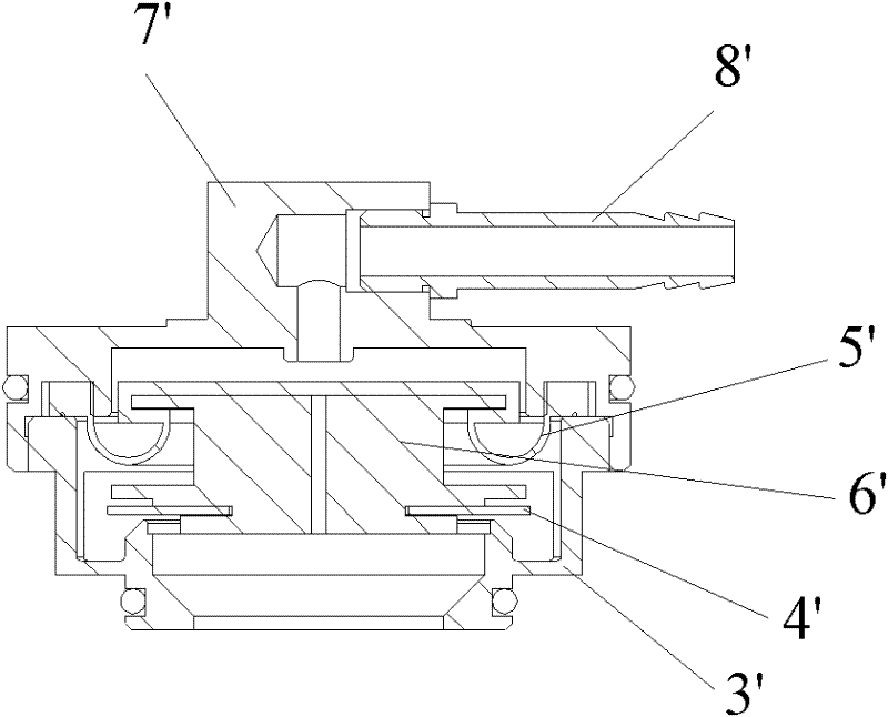
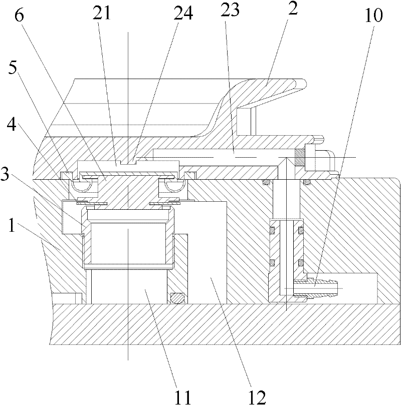
[0020] Figure 3 to Figure 5 A typical embodiment of the PEEP valve of the present invention is shown as a component of an anesthesia machine. In this example, image 3 is a sectional view of the PEEP valve, which is used to control the flow rate of the air flow from the second airway 11 to the third airway 12 . Figure 4 is a schematic diagram of a folding sac fixing disc for an anesthesia machine, Figure 5 show image 3 Schematic diagram of the installation of the PEEP valve shown. As shown in the figure, the PEEP valve according to the present invention includes a valve core 6, a valve port 3, and a valve core installation groove 21 opened in the folding bag fixing plate 2, and the val...


PUM


Abstract

The invention provides a positive expiratory end pressure (PEEP) valve and an anesthesia machine with the same. The PEEP valve comprises a first module (1), a second module (2), a valve core (6), a valve core mounting groove (21) and a first air passage (23), wherein a gas pipeline is arranged in the first module (1); the second module (2) is buckled with the first module (1); the valve core (6) is movably arranged in the cavity of the first module (1) and provided with a rolling film (5); the valve core mounting groove (21) is formed in one side of the second module (2) facing the first module (1) and corresponds to the valve core (6); and the first air passage (23) is formed in the second module (2) and used for communicating the valve core mounting groove (21) to a control gas source. Compared with the prior art, the PEEP valve has the advantage of simplicity in structure and installation.

Description

technical field [0001] The invention relates to the field of air control valves, in particular to a PEEP valve and an anesthesia machine with the PEEP valve. Background technique [0002] The PEEP valve (Positive Expiratory End Pressure) is a common device for ventilators and anesthesia machines, and it is installed in the circuit manifold. With the help of the PEEP valve, the anesthesia machine or ventilator can effectively control the patient's positive end-expiratory pressure. [0003] figure 1 It shows an exploded view of a PEEP valve in the prior art, which includes a valve body 3', a valve core assembly and a valve cover 7', wherein the valve core assembly consists of a diaphragm 4', a rolling film 5' and a 4' and the valve core 6' of the rolling film 5', the diaphragm 4' is stuck on the outside of the lower plate 61' of the valve core 6', and the curved part of the rolling film 5' is accommodated on the valve core upper plate 62' and in the groove 63' between the l...

Claims


Application Information

Patent Timeline
Patent Type & Authority Applications(China)
IPC IPC(8): A61M16/01A61M16/20
Inventor 周兆义
Owner BEIJING AEONMED
Why Eureka
Try Eureka