
Working table structure of vertical internal broaching machine

A technology of workbench and internal broaching machine, which is applied in the direction of manufacturing tools, metal processing, planer/slotting machine, etc., can solve the problems of no additional functions, potential safety hazards, production efficiency, and inability to meet the processing requirements of vertical internal broaching machines, so as to improve Work efficiency, simple structure, save unloading and cleaning time

Active Publication Date: 2013-07-10
ZHEJIANG CHR INTELLIGENT EQUIP
View PDF4 Cites 0 Cited by
  • Summary
  • Abstract
  • Description
  • Claims
  • Application Information

AI Technical Summary

Problems solved by technology

[0002] Vertical internal broaching machine is a commonly used metal cutting machine tool. The workbench is an important part of the vertical internal broaching machine for placing workpieces to be processed. The workbench of the existing vertical internal broaching machine can only place workpieces. Without other additional functions, it obviously cannot meet the processing requirements of today's vertical internal broaching machines
Moreover, during the processing of the vertical internal broaching machine, a lot of iron filings will be generated on the broach. If manual cleaning is adopted, it will not only waste time and effort, but also easily cause safety hazards and low production efficiency.

Method used


Image

  • Working table structure of vertical internal broaching machine
  • Working table structure of vertical internal broaching machine

Examples


Embodiment Construction

[0011] The present invention will be further described in detail below in conjunction with the accompanying drawings and embodiments.

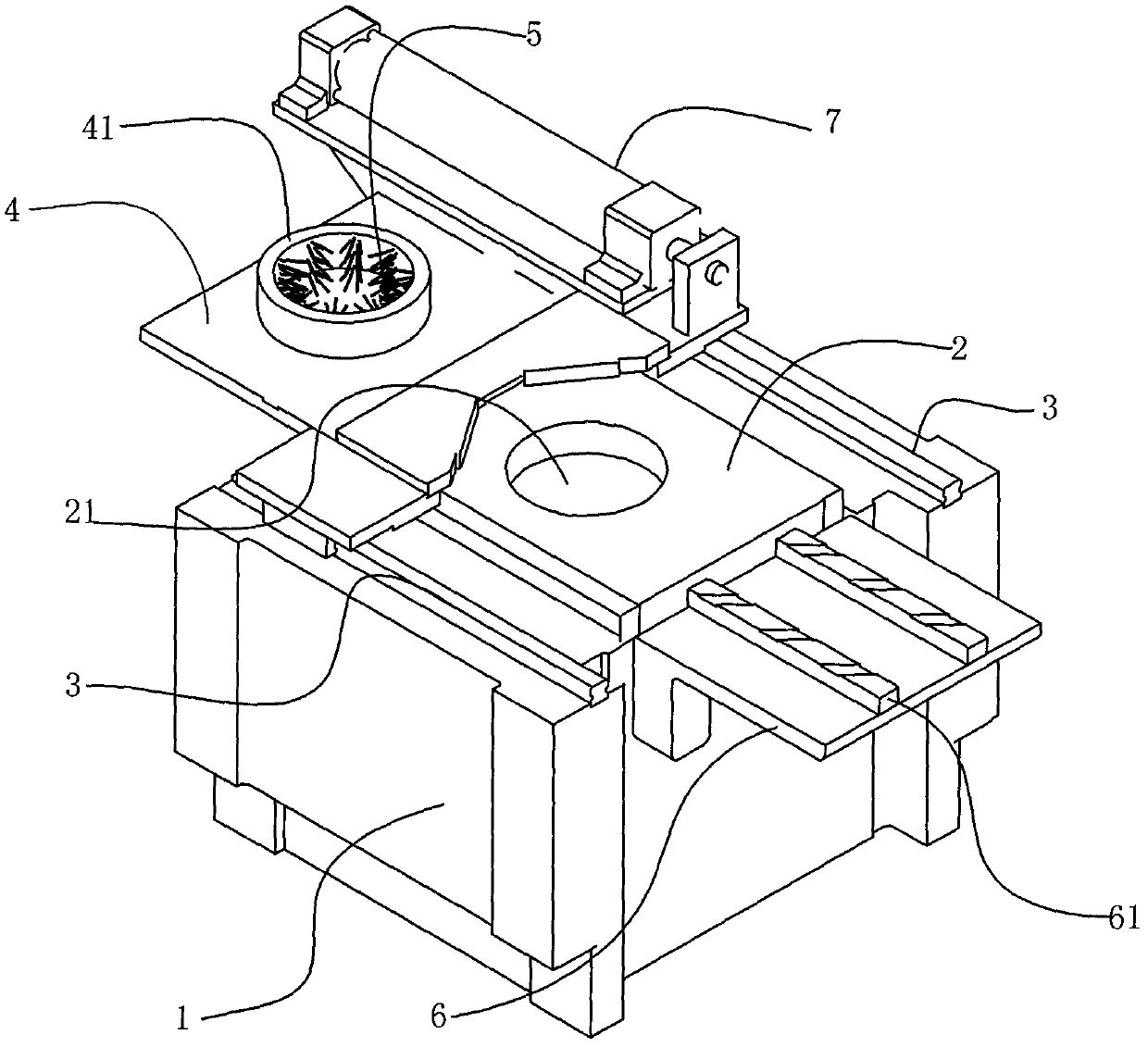
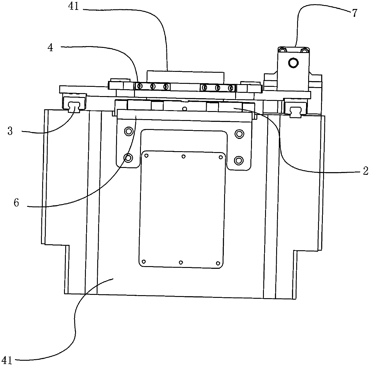
[0012] The workbench structure of vertical inner broaching machine of the present invention, as Figure 1-2 As shown, it includes a workbench body 1 and a faceplate 2 located on the workbench body 1. The faceplate 2 has a through hole 21 for a broach to pass through. The workpiece to be processed is placed on the face plate 2 .

[0013] On the workbench body 1, guide rails 3 are provided on the left and right sides of the faceplate 2, and a pusher plate 4 is provided above the faceplate 2. The pusher plate 4 cooperates with the guide rail 3 to perform horizontal reciprocating movement along the guide rail 3, covering The faceplate 2 may be located at the rear side of the faceplate 2 . The pushing plate 4 also has a hole 41 matching the through hole 21 on the faceplate 2 , and a ring of bristles 5 is arranged on the inner peripheral surface o...


PUM


Abstract

The invention relates to a working table structure of a vertical internal broaching machine. The working table structure comprises a working table body and a flower disc which is positioned on the working table body and used for accommodating a workpiece to be machined, wherein the flower disc is provided with a through hole through which a broach passes; the working table structure is characterized in that: a bracket board which is abreast with or a little lower than the flower disc is arranged on the front side of the flower disc; guide rails are arranged on the working table body on both sides of the flower disc; a discharging board is arranged above the flower disc; the discharging board can do horizontal reciprocating motion along the guide rails so as to be covered above or on the rear side of the flower disc; a hole matched with the through hole of the flower disc is formed in the discharging board; and a circle of brush hairs are arranged on the inner circumferential surface of the hole. The working table structure can automatically discharge the machined workpiece and clean iron scraps on the broach during return of the working table, so that the structure is simple, the discharging time and the cleaning time of the broaching machine are saved, and the working efficiency of the broaching machine is improved.

Description

technical field [0001] The invention relates to a workbench structure of a vertical inner broaching machine. Background technique [0002] Vertical internal broaching machine is a commonly used metal cutting machine tool. The workbench is an important part of the vertical internal broaching machine for placing workpieces to be processed. The workbench of the existing vertical internal broaching machine can only place workpieces. Without other additional functions, it obviously cannot meet the processing of today's vertical internal broaching machines. Moreover, during the processing of the vertical internal broaching machine, a lot of iron filings will be generated on the broaching tool. If manual cleaning is adopted, it will not only waste time and effort, but also easily cause safety hazards and low production efficiency. Contents of the invention [0003] The technical problem to be solved by the present invention is to provide a workbench structure of a vertical inter...

Claims


Application Information

Patent Timeline
Patent Type & Authority Patents(China)
IPC IPC(8): B23D7/08B23Q1/25B23Q7/00B23Q11/00
Inventor 林绿高
Owner ZHEJIANG CHR INTELLIGENT EQUIP
Learn More